
Measuring Surface Finish On Large ODs
The irregularity of a machined surface is the result of the machining process, including the choice of tool, feed rate, speed of the tool, machine geometry and environmental conditions. This irregularity consists of high and low spots that are machined into a surface by the tool bit or a grinding wheel. These peaks and valleys can be measured and used to define the condition and, sometimes, the performance of the surface.

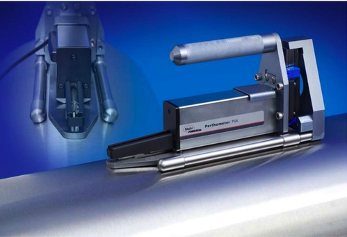
Adding an alignment attachment to the surface profiling drive ensures that the probe follows the crown of the part and provides an accurate and repeatable result.

George Schuetz


The irregularity of a machined surface is the result of the machining process, including the choice of tool, feed rate, speed of the tool, machine geometry and environmental conditions. This irregularity consists of high and low spots that are machined into a surface by the tool bit or a grinding wheel. These peaks and valleys can be measured and used to define the condition and, sometimes, the performance of the surface. There are more than 100 ways to measure a surface and analyze the results, but the most common measurement of the mark made by the tool, or the surface texture, is the roughness measurement, Ra.
On shafts, Ra is the most commonly measured parameter. Basic, handheld surface gages can be used on larger parts, and getting reliable and repeatable results is a piece of cake. Even for very small parts, physical features built into portable gages or inexpensive bench stands allow parts to be aligned to the probe for a good average roughness result.
The reason for this is in the nature of the probe. Probes for simple roughness use the part surface as a reference and follow its contour as the individual peaks and valleys are measured. Therefore, it is not that critical to exactly align the surface finish gage to the axis of the part being measured. For example, if a probe is not perfectly aligned with the axis of the part, then instead of riding on the crown of the part, the probe would run over the crown. However, because a roughness style probe uses the part surface as a reference, it would not see this riding up and down, and it would still produce a good Ra result.
There are literally hundreds of surface finish parameters, but not all of them can be measured with the simple roughness probe mentioned above. Most of these parameters involve expressing the longer profile waves that are a result of the machining process itself. For these parameters, a skidless probe is required. A skidless probe incorporates a smooth, flat internal surface as the reference so that the probe can respond to waviness as well as roughness.
Thus, when a waviness callout is specified for an OD, the alignment of the probe becomes critical. If the axis of the part is not aligned with the reference surface in the skidless probe when the probe passes over the crown of the part, then the crown looks like a curved surface compared to the reference of the probe. It can be difficult then for the untrained eye to differentiate the curve of the crown from long-wave surface irregularities in the part.
Let’s look at a specific case in point: Let’s say we are trying to inspect a large printing roller. You can certainly see how short-wave surface finish could be a problem. These short wave peaks and valleys could cause too much ink to stick to the roller, or maybe not enough.
On the other hand, if the short-wave finish is good but there are some long-wave high and low spots—profile issues—then there may not be the correct contact between the rollers or the paper. This is where profiling of the large OD becomes critical. Also, it is just as critical to make sure that the probe testing the part is perfectly aligned with the part.
Profiling drives tend to be fairly large, especially when they take very long traces. Trying to manually hold and align the system to the part’s axis while remaining stable is a Herculean effort. This is where simple but effective fixturing can make the user’s job a lot easier.
As the figure above shows, adding an alignment attachment to the surface profiling drive ensures that the probe follows the crown of the part and provides an accurate and repeatable result.


Read Next

The Cut Scene: The Finer Details of Large-Format Machining
Small details and features can have an outsized impact on large parts, such as Barbco’s collapsible utility drill head.
Read More

3 Mistakes That Cause CNC Programs to Fail
Despite enhancements to manufacturing technology, there are still issues today that can cause programs to fail. These failures can cause lost time, scrapped parts, damaged machines and even injured operators.
Read More