
The Ins and Outs of Fixed Body Mechanical Plug Gages
Fixed body mechanical plug gages are one of the best ways to measure hole diameters. With this type of gage there is no rocking, as with an adjustable bore gage.


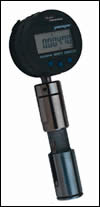
With a fixed plug type bore gage, the body size of the gage is very close to the diameter it is made to measure. Therefore, the plug “locks” the gaging part of the plug in the hole.
The plug body holds and centralizes an internal mechanical transfer mechanism. Typically this consists of a set of contacts mounted to some linear spring arrangement in contact with a 90 degree transfer rod. The rod has a precisely ground vee that transfers the diameter change seen at the contacts to an indicator out the rear of the plug.
Fixed body mechanical plug gages are one of the best ways to measure hole diameters. With this type of gage there is no rocking, as with an adjustable bore gage. It is fast and provides high performance for tight tolerance holes. Because these gages are easy to apply, they are usually used to measure high volumes of parts. Even in cases where the parts are expensive and the tolerance tight, a fixed body plug may be an economical choice for the application. There simply may be no other way of measuring the critical part tolerance required.
With a fixed plug type bore gage, the body size of the gage is very close to the diameter it is made to measure. Therefore, the plug “locks” the gaging part of the plug in the hole. This requires very little operator skill and results in virtually no operator influence. Obviously, there has to be some body clearance between the plug body and the hole diameter so the plug will fit into the hole being measured, and control of this clearance is critical for the gage builder. Limited clearance will provide shorter measuring range but better performance. More clearance increases measuring range but allows for more “centralizing error” (actually measuring the chord rather then the diameter).
In fact, the plug body acts as a way of holding and centralizing an internal mechanical transfer mechanism. Typically this consists of a set of contacts, mounted to some linear spring arrangement that is in contact with a 90-degree transfer rod (see illustration below). The transfer rod has a precisely ground vee in it that takes the diameter change seen at the contacts and transfers it to an indicator out the rear of the plug. The ground-in vee is made at such an angle that there will be a one-to-one 90-degree transfer, and no compensation is needed by the indicating device.
The rear of the vee rod will either have a spherical or flat end. It’s important to note the style of the end, as the indicating device monitoring the rod needs to be the opposite type of contact. For example, a flat-ended vee rod should be used with an indicator having a spherical contact and vice-versa. This assures a point-to-point motion transfer.
The transfer mechanism is also a two-point floating differential system. This means that once in the hole, the plug may be moved (albeit slightly) side to side in the direction of the contacts. When this is done, one contact will move out a little while the other one moves in. Thus, they cancel each other out and the result is always the diameter of the hole, regardless of plug position. This configuration is very important for exploring the bores for various geometric conditions, including ovality, barrel, taper or hourglass shapes.
In most cases, tungsten is used for the contacts to provide best wear characteristics for longest gage life. However, if the part material is not best served by this type of contact, other materials such as tool steel, ruby or diamond may be required, and are readily available.
Finally, the most critical thing to remember about the fixed bore gage is that it is a dedicated instrument. Specifying the requirements for the application is really no different than specifying for an adjustable core gage, snap gage or any other measuring device. However, unlike these gages, the fixed bore plug is custom made for the application. Get any one of the parameters wrong and the gage becomes a very nice looking desk ornament. Always double check the application when specifying to make sure you get the right custom gage.


Read Next

3 Mistakes That Cause CNC Programs to Fail
Despite enhancements to manufacturing technology, there are still issues today that can cause programs to fail. These failures can cause lost time, scrapped parts, damaged machines and even injured operators.
Read More
The Cut Scene: The Finer Details of Large-Format Machining
Small details and features can have an outsized impact on large parts, such as Barbco’s collapsible utility drill head.
Read More
