
.jpg;width=70;height=70;mode=crop;format=webp)


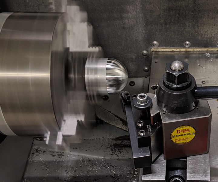
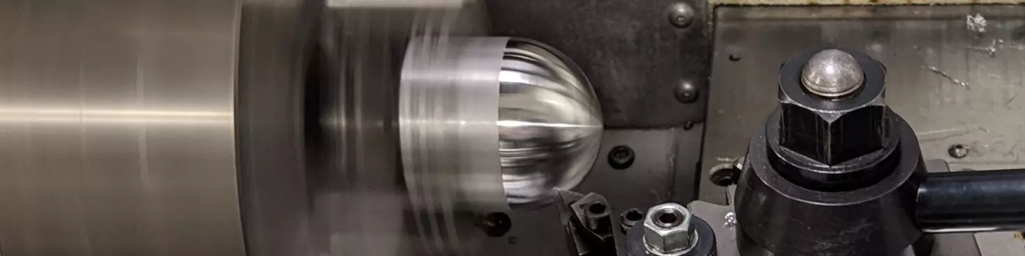
This stainless steel machining operation at the UNCC lab simulates the defense-related manufacturer’s machining of hemispherical forms into radioactive material. Read below for the discoveries about productivity that are resulting from finding the most safe and effective way to machine this part.
Researchers at the University of North Carolina Charlotte (UNCC) searching for a reliable means of breaking chips might have broken something else as well: the physical limits on productivity in turning. “Modulated turning,” their chip breaking technique involving oscillations in the tool path, has shown promise as a means of enabling a higher metal removal rate in turning without introducing any other change to the process.
Chipbreaker in the Post
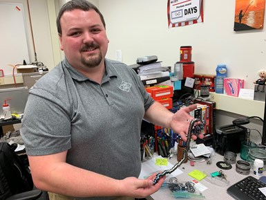
Researcher Ryan Copenhaver illustrates the problem. Long stringy chips such as this are potentially a problem in any turning operation, but they are all the more problematic where safety precautions against radiation exposure prevent operators from easily clearing them.
Professor Tony Schmitz leads this research at UNCC. Working with him is mechanical engineering graduate student Ryan Copenhaver. The intended beneficiary of the work is a special manufacturing facility affiliated with the U.S. government that is involved with making nuclear weapons. Because this facility machines radioactive material, chip breaking is a vital concern — perhaps the most vital concern in the machining process. Owing to the danger of exposure, an operator can’t interact with the process to clear chips or change a tool as easily as these steps could be performed for another machining process. For a turning operation aimed at machining radioactive workpieces into hemispherical forms, the facility was looking for a means of breaking chips that was even more consistent and reliable than the use of cutting tools’ chipbreaker forms. Enabling the tool to repeatedly leave the cut — literally breaking contact over and over — was seen as the key to this.


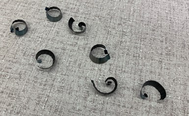
The better case is this: small chips that easily fall away. The UNCC researchers have achieved this chip breaking thanks to a postprocessed tool path that introduces regular oscillations into the cut.
Previous UNCC researcher Scott Smith (now with Oak Ridge National Laboratory) began the work, discovering that programmed CNC motion alone can be sufficient to provide this repeated reversal in the path. A postprocessor he helped to develop adds recurring reversals into the programmed path according to the amplitude and frequency chosen by the programmer. The hemispherical turning involves interpolation in the X and Z axes, with the reversals in the path following the same interpolated curve. Parameters for the chip breaking reversals fall in the range of 0.5 to 3.0 reversals per second (the frequency) with a typical reversal amounting to a retreat of 0.005 inch (the amplitude) back along the path.
Dr. Schmitz took up the research after the chipbreaking effect was proven. He has investigated the impact on surface finish, but has also explored other positive effects beyond the original aims of the project. “The amplitude and frequency of these reversals are now additional knobs we can turn to affect the process,” he says. And one of the improvements that can come from tuning these knobs is increased productivity.
Here is video showing modulated turning in action:
Finish and Productivity
As for surface finish, the tool retreating and advancing as it cuts does produce a rougher finish than continuous cutting. Importantly, though, the detriment is consistent — meaning it can be overcome with a consistent follow-up step. Working in 304 stainless steel (a close stand-in for the radioactive material), Dr. Schmitz and Mr. Copenhaver have investigated the effectiveness of a “spring pass” for improving the final finish. A spring pass is simply the same tool path run again with the same tool, with no change in position, allowing the cutting edge to remove fine amounts of additional material. Testing involved continuous cutting with and without spring passes, and modulated turning with and without the spring pass also including modulated turning. The findings so far suggest that modulated turning followed by a non-modulated spring pass produces finishes as good as or nearly as good as constant-feed cutting.
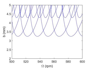
A stability lobe diagram in turning might typically look like this. The graph shows depth of cut versus rotational speed; stable cutting is found below these lines. Thus, different speeds might allow for stability at different depths of cut. But all of this assumes a continuous feed. Modulated turning can allow for different depths at a given speed.
But now for the effect on productivity. In turning, and indeed, in all chipmaking processes, metal removal rate is limited by the underappreciated phenomenon of “regeneration of waviness,” Dr. Schmitz says. This is the tendency of waves left in the surface by machining passes to produce cutting force variation that amplifies oscillations related to the harmonic characteristics of the machine tool and overall machining system. The self-amplifying effect leads to chatter, and at certain combinations of speed and depth of cut, it produces chatter great enough to inhibit productive machining and quickly leads to tool failure. When cutting parameters are too aggressive, regeneration of waviness is frequently the reason why that combination of parameters doesn’t perform.
However, the modulated turning — programming the tool path so the cutting edge reverses perhaps two or three times with every rotation of the part — has the effect of interrupting this regeneration. Thus, a set of parameters that might previously have been too aggressive can become stable enough to cut effectively as long as the reversals are part of the path. Postprocessing the tool path just to introduce modulated turning can thereby enable a set of previously too-aggressive parameters to cut effectively without any change to the tool, speed, depth of cut or nominal feed rate. The UNCC researchers have demonstrated this, and this graph illustrates the finding:
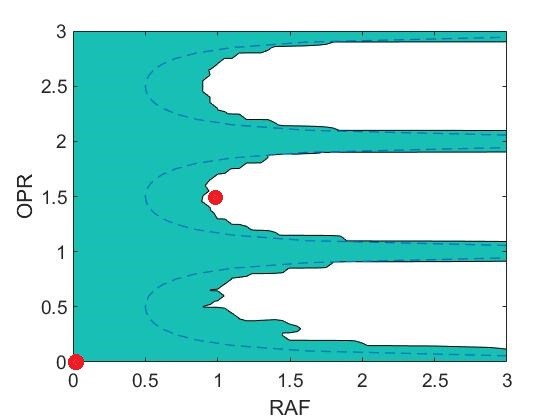
This graph of the two modulated turning parameters — oscillations per revolution (OPR) versus relative amplitude to the feed (RAF) — shows the effect of modulated turning at given set of cutting parameters. The cutting conditions illustrated are 400-sfm speed, 0.003-ipr feed rate and 0.1772-inch depth of cut in 1026 steel. The green area of the graph is unstable cutting. Without modulated turning (OPR = 0, RAF = 0), this cut at these parameters is unstable. However, with modulated turning of OPR = 1.5 and RAF = 1, the same cutting parameters allow for stable cutting.
The technique of introducing a new oscillation to bypass the limits from other oscillations in the system is beyond the scope of the current sponsor’s aims for modulated turning. The nuclear manufacturer wants a safe and predictable process, not necessarily a more productive one. But other manufacturers obviously have productivity as a priority. For them, modulated turning could increase the potential output of existing turning machines by allowing the cutting parameters to increase without chatter setting in. It is potentially a technology available to any CNC lathe for cutting faster, so Dr. Schmitz says the next step with this research is to find production-oriented sponsors allowing his team to further explore this advantage and scale it up to discover what the limits of this technique might be.


Related Content

Choosing Your Carbide Grade: A Guide
Without an international standard for designating carbide grades or application ranges, users must rely on relative judgments and background knowledge for success.
Read More
How to Reduce Cycle Times by 70% and More on Your Existing CNCs and Dramatically Improve Tool Life Too
By employing advanced high efficiency milling techniques for the entire machining routine, SolidCAM’s iMachining technology can drastically reduce cycle times while vastly improving tool life compared to traditional milling.
Read More
When Organic Growth in Your Machine Shop Isn’t Enough
Princeton Tool wanted to expand its portfolio, increase its West Coast presence, and become a stronger overall supplier. To accomplish all three goals at once, acquiring another machine shop became its best option.
Read More
Inside an Amish-Owned Family Machine Shop
Modern Machine Shop took an exclusive behind-the-scenes tour of an Amish-owned machine shop, where advanced machining technologies work alongside old-world traditions.
Read MoreRead Next

How to Reduce the Effect of Vibration in Production Grinding
It is not always possible to correct a vibration problem as soon as that problem begins to appear. Rather than stopping production, here is a means of continuing to realize smooth, efficient grinding until the underlying cause of vibration can be addressed.
Read More
Ten Questions About Chatter
If you want to use a high speed milling spindle to machine aggressively, then information about chatter should be more than just background noise. Here are some basics.
Read More
The Overhang Effect
The length by which the tool extends from the toolholder is a variable that can be used to 'tune' the machining process. Contrary to what you may expect, increasing the tool's L:D ratio may reduce chatter and result in more productive milling.
Read More