
Using Cameras to Align Tools and Spindles on Swiss-Type Lathes
Installing cameras in the spindles of a Swiss-type lathe can simplify the alignment of tools with the main and subspindles as well as the alignment of those spindles with each other.
.jpg;width=70;height=70;mode=crop;format=webp)
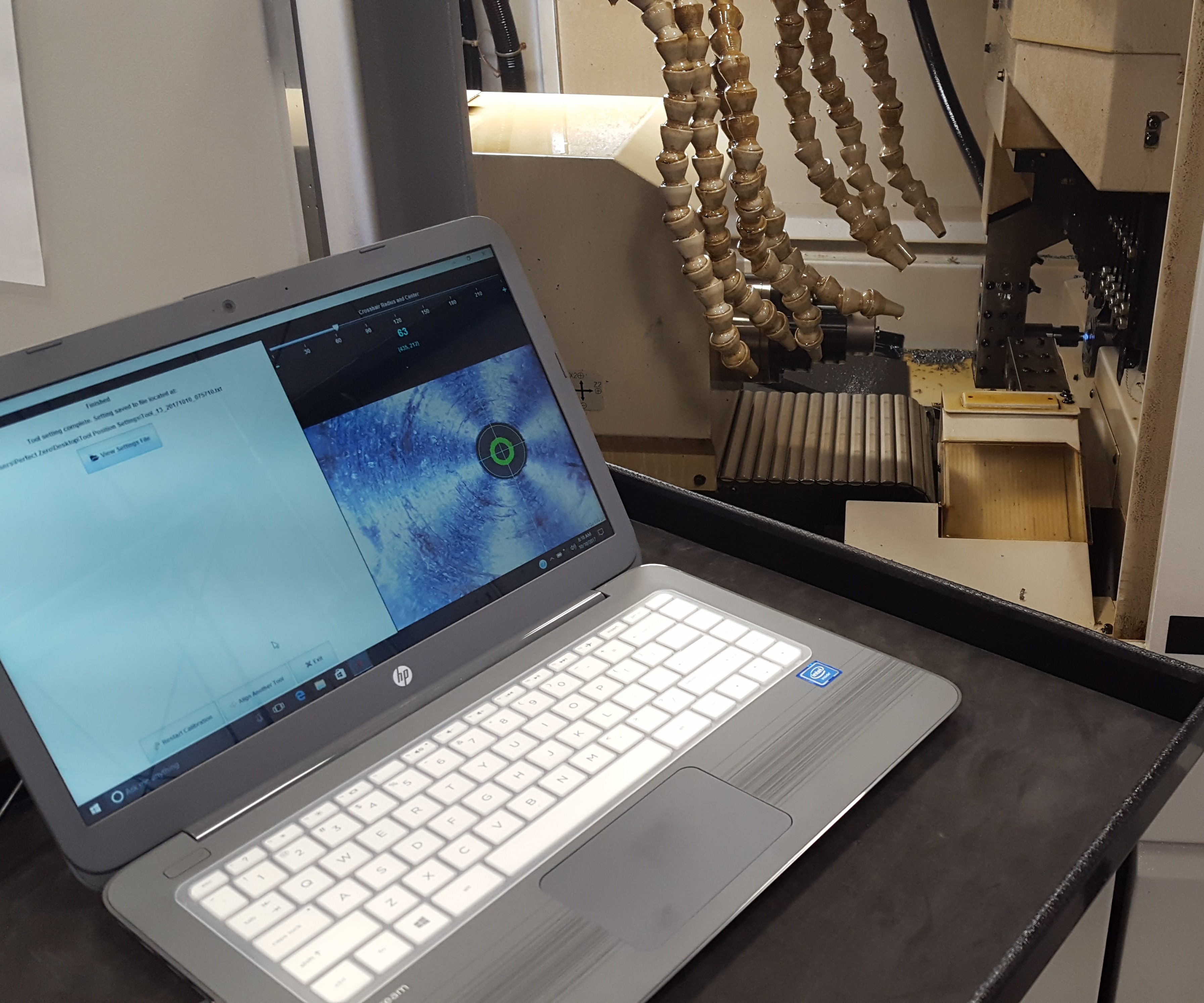
Cameras installed in the spindles of Swiss-type lathes can simplify the alignment of tools to the spindles’ centerlines.
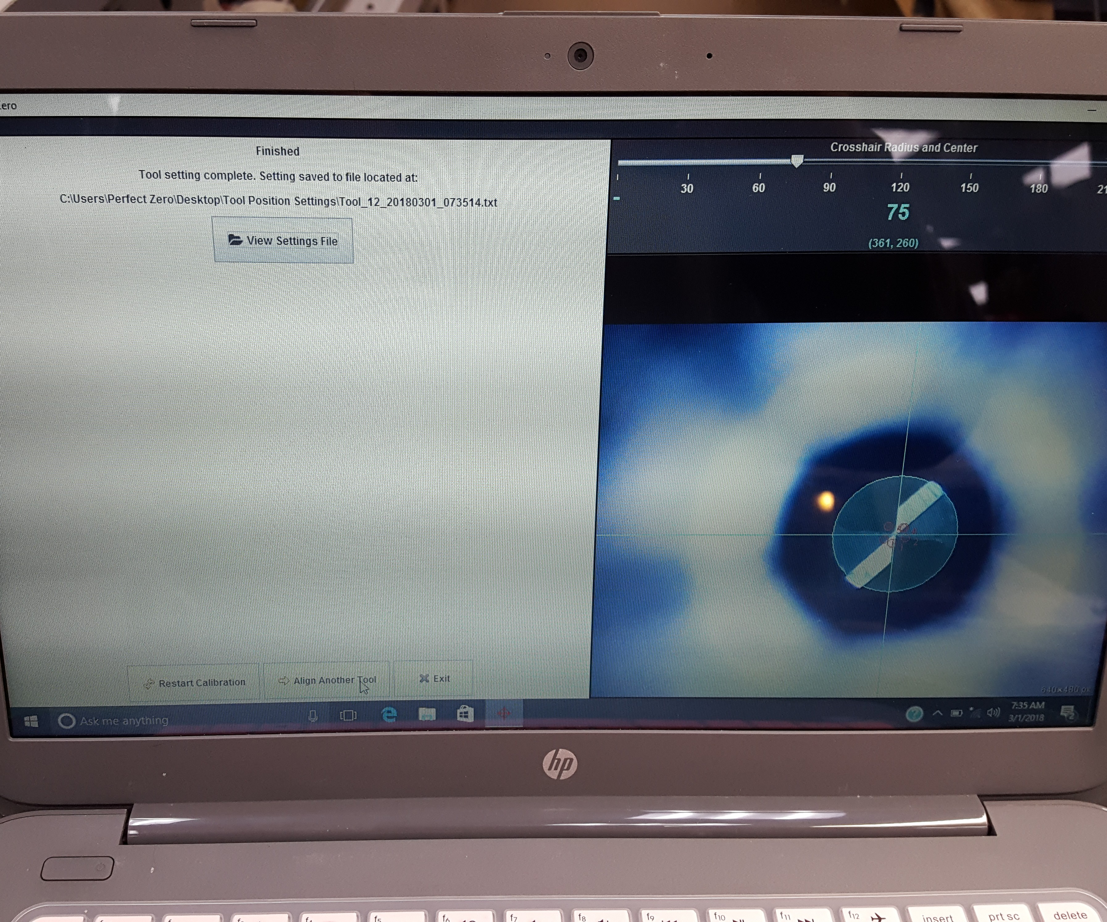
Crosshairs on the screen represent the spindle centerline, and the distance that the tool center point or insert edge is away from the centerline can be seen. The software calculates the amount of distance the tool is from the theoretical spindle centerline and that data is input into the control to correct for the misalignment.
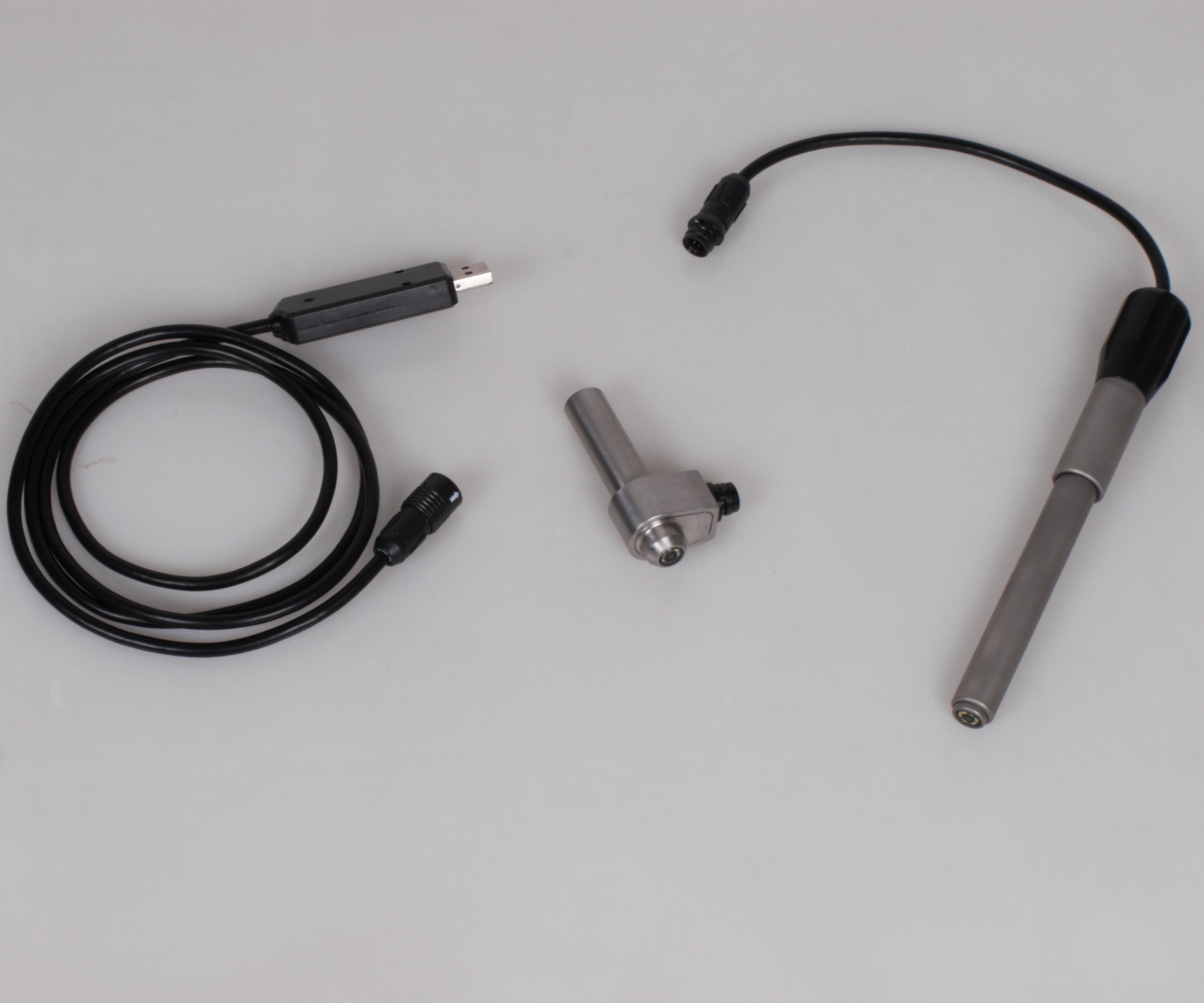
One camera is designed to install in a Swiss-type lathe’s guide bushing. The other features a shank-style holder to install in a subspindle.


Misalignment can cause machining misfires. For Swiss-type lathes, it is important that tools on the gang slide are aligned with the main spindle’s centerline and backworking tools are aligned with the subspindle’s centerline to ensure accuracy and prevent breakage of tools such as small boring bars. Similarly, the main and subspindle centerlines must be aligned with each other for accurate part pickoff operations.
Ben York, president of Swiss Turn Solutions, a consulting company that offers the Theory 168 line of machine tool accessories, says a common way to check alignment is to use interapid- or coaxial-type dial indicators installed in spindles. For example, installing an indicator in a subspindle to probe a rotating turned bar in the main spindle is one way to align both spindles with each other. However, Mr. York explains that there can be issues using these devices to perform such alignments. In some cases, he says an indicator simply might not fit in a Swiss-type’s guide bushing or general workzone. If it does fit, the distance that the indicator sticks out of the spindle typically causes alignment error. Plus, a transfer measurement from the main spindle to the subspindle to the tools is typically required for aligning tools with the main spindle, which can lead to error stacking.


Mr. York says his company developed a non-contact camera system that offers a more precise and repeatable way to determine not only the current state of spindle and tool alignment, but also the amount of misalignment to correct it. The Perfect Zero Swiss system uses cameras that are installed in the main and subspindles to enable the user to view tools under magnification to determine their actual position when they are moved to the theoretical spindle centerline position. The system’s software then determines how much the tool must be moved to bring it to the actual centerline position.
To perform tool alignment with the main spindle, the user installs an 50× magnification camera in the guide bushing and plugs the camera into the system’s dedicated computer with Perfect Zero software via a USB port. A 5-minute calibration cycle that uses a supplied target as a reference point enables the software to determine and record the location of the spindle centerline. Next, each tool is driven to the spindle centerline and a magnified image of the tool is shown on the computer screen. Crosshairs on the screen represent the spindle centerline, and the distance that the tool center point (for drills) or insert edge (for boring bars) is away from the centerline can be seen. The gang slide is then manually moved to align the tool with the spindle centerline. The software, in combination with machine position, calculates the difference, which the user inputs into the control.
Guide-bushing cameras are available in diameters as small as 10 mm. A more general shank-type camera can be installed in a subspindle to perform similar alignment of backworking tools to the subspindle centerline as well as aligning main and subspindle centerlines. The latter is important to ensure proper subspindle part pickoff from the main spindle for subsequent backworking operations. Mr. York cites a shop that was experiencing a problem with small parts being scratched when the subspindle picked them off the main spindle. This shop tried using a dial indicator installed in the main spindle, but the device could not align the spindles as accurately as needed. However, a Perfect Zero camera installed in the guide bushing could be positioned 0.1 inch away from a target installed in the subspindle (essentially where the part would be picked) and proper alignment was attained.
Mr. York says the system is valuable even for very accurate Swiss-types as it can detect positioning error because of tool runout or variability when small tools are installed in collet-style toolholders. It achieves position repeatability of 0.0002 inch and can be used for tools as small as 0.005 inch in diameter. The system includes a guide-bushing camera, a shank-type subspindle camera, a dedicated laptop computer with Perfect Zero software, various visual calibration targets and a portable service cart. The subspindle camera is a universal model and can be used in lathes as well as mills to determine work coordinates, especially for small parts and parts made from delicate materials. It also can be used on a 3D printer to determine the position of a substrate onto which another material will be printed.


Related Content

How to Mitigate Chatter to Boost Machining Rates
There are usually better solutions to chatter than just reducing the feed rate. Through vibration analysis, the chatter problem can be solved, enabling much higher metal removal rates, better quality and longer tool life.
Read More
Buying a Lathe: The Basics
Lathes represent some of the oldest machining technology, but it’s still helpful to remember the basics when considering the purchase of a new turning machine.
Read More
New Modular Tool Options for Small Spindle Milling
Tooling options have been limited for small spindle milling applications. Now modular, indexable systems are available that provide broad flexibility to get the right cutter for the job with less inventory and at lower cost.
Read More
Selecting a Thread Mill That Matches Your Needs
Threading tools with the flexibility to thread a broad variety of holes provide the agility many shops need to stay competitive. They may be the only solution for many difficult materials.
Read MoreRead Next

3 Mistakes That Cause CNC Programs to Fail
Despite enhancements to manufacturing technology, there are still issues today that can cause programs to fail. These failures can cause lost time, scrapped parts, damaged machines and even injured operators.
Read More

The Cut Scene: The Finer Details of Large-Format Machining
Small details and features can have an outsized impact on large parts, such as Barbco’s collapsible utility drill head.
Read More