
The Automation Inspiration
Although automated manufacturing cells typically consist of standard products such as CNC machine tools, robots, pallets and cell control software, almost all of these systems rely on inventive concepts developed for the particular application. These "good ideas" often account for the outstanding productivity and flexibility of these systems. This article looks at several of the "good ideas" that characterize a cell comprised of seven wire EDM units and a robot on a rail transfer unit.
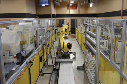
A six-axis robot riding on a 60-foot track is the signature feature of Big Sky EDM’s latest automated cell. The track, or rail transfer unit (RTU), runs along the center of the cell with seven Fanuc wire EDM units arranged on either side. With this layout, the front, rear and service sides of each machine are accessible for unobstructed maintenance.
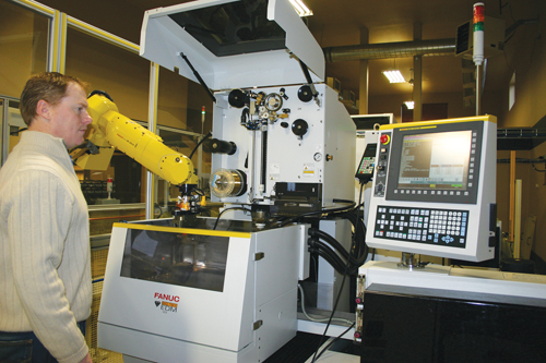
As Russ Scoffield looks on, the robot loads a PCD-tipped cutting tool into the wire machine equipped with a rotary table. One reason he favors the Fanuc Robocut for his shop is the standard, built-in automation featured in these machines. The highly-reliable automatic rethreading capability has been especially valuable in a cellular application, he says.
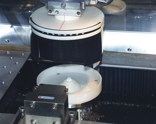
Baskets shaped like shallow trays capture the finished segments and allow them to be transported robotically. A matching cover with shroud lowers over the basket and fully encloses it before the upper head descends for cutting.
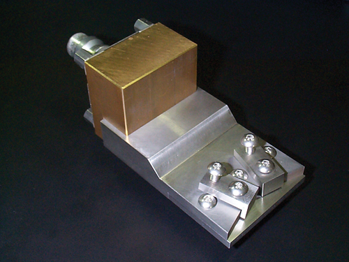
The palletized gripping fixture holds the raw material disk by its edge. The pallet interface on the other end fits both the receiver on the wire unit and the brackets in the storage magazine. A special gripper enables the robot to handle the pallet entirely by itself.

All three robot grippers ride along with the robot so that they are never out of reach.
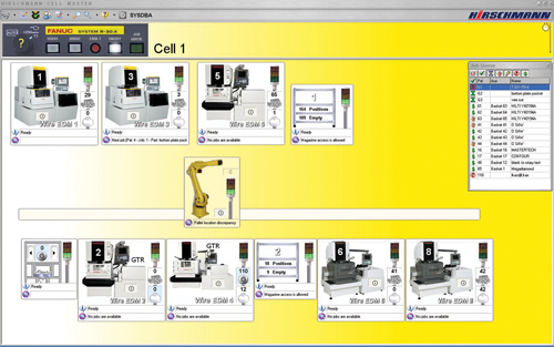
The Cell Management System is a Windows-based PC program that controls both the robot and the wire machines in the cell. The main cell interface screen shows a live overview of the cell. Clicking on a graphic for a machine, the robot or a storage magazine opens it to show details about its status, the pending job and so on.
By opening the graphic for Rack 1, the operator can detect the baskets that hold a finished assortment of segments and the pallets with used-up disks. Dragging and dropping the selected basket or pallet icon is all it takes to move that item to the infeed/outtake station automatically.


Automated production systems often put on an interesting show. That’s true of Russ Scoffield’s automated cell that incorporates seven wire EDMs. The cell is located at his shop, Big Sky EDM, in Hayden Lake, Idaho, which is not an easy place to get to. It’s much easier to watch a video of the cell in operation to the right of this article.
However, watching automation can be deceptive. It’s easy to marvel at the visible technology without fully appreciating the many smart ideas that it represents. In this cell, some of the ideas are readily viewable, but others are not. In fact, they are all important. Examples of smart ideas you can see are the part containment baskets, the palletized workpiece holders, the ride-along robot gripper rack and a cell layout that makes it easy to safely access the machines for routine maintenance. Examples of smart ideas that work behind the scenes are the mix up-proof material control system, job pre-setting and the drag-and-drop scheduling system.


Taken together, these ideas and many others enable the cell to run “lights-out” around the clock, including nights and weekends. The cell is designed to produce precisely shaped segments of polycrystalline diamond (PCD) and cubic boron nitride (CBN) that tooling manufacturers can use as pre-cut tips for form tools, end mills, spade drills and other types of cutting tools. One wire machine in the cell also accepts rotary cutting tools with PCD tips already brazed in place. Another machine handles flat tools with PCD tips. The special equipment on these machines allows the tips to be trimmed to correct slight mislocations introduced in the brazing process. In short, the cell handles high product variation in low volumes under full automation, enabling very rapid customer order fulfillment.
Early Inspiration
Mr. Scoffield, a manufacturing engineer by training, was inspired to automate production of PCD and CBN segments while assigned to a facility that was cutting them for a major cutting tool manufacturer. The facility had a number of automated wire EDM units that cut the segments from 58-mm disks produced by synthetic diamond manufacturers such as DeBeers, Smith MegaDiamond, and Sumitomo. Mr. Scoffield had a vision for an integrated system that extended the automation in ways to improve product quality, productivity, pricing and—perhaps most importantly—rapid, on-time delivery.
That was a few years before he had the chance to start his own company and realize his dream of producing made-to-order segments in a rapid-response environment. When that chance came, he had automation in mind from the start, although he couldn’t implement all of his ideas right away. To launch his start-up company, Mr. Scoffield borrowed money from his parents and installed a wire EDM in a remodeled outbuilding on the family ranch in Montana. That was in 2000. By then, it was clear that the Internet and well-established shipping networks made location a minor consideration. Because the high plains of the Northwestern states were home, he called his company Big Sky EDM (bigskyedm.com) after the region’s apropos nickname.
His first machine was a Fanuc Robocut 0CS/AWF. Mr. Scoffield was familiar with this line of wire machines because it was the one used by most of the other manufacturers of precut segments. This machine was acquired from the North American importer of Fanuc Ltd.’s wire EDM equipment, Methods Machine Tools, Inc. (Sudbury, Massachusetts). Mr. Scoffield’s association with this firm would prove to be very fortunate because Methods had many good ideas about automation that would eventually compliment and enhance his own.
Once established, Big Sky EDM grew quickly. He continued to add EDM units and other support equipment. In July 2005, he moved the operation away from the ranch and into a new building in nearby Hayden Lake, across the state line in Idaho. Earlier that year, Mr. Scoffield took the first steps to implementing an automated PCD cutting process. This time, his inspiration came from visiting an open house at Methods’ corporate office in Sudbury.
The result was an automated cell built around a single Robocut 0iCS-AWF with an inverted Fanuc LR Mate robot. The cell was installed in November 2005. This “Phase I” cell gave Big Sky and Methods an opportunity to develop and prove out the automation process that would ultimately be implemented in the Phase II multi-machine cell currently in operation. Some of the key innovations embodied in this cell include a means to catch the segments as they are cut free of the parent disk; a method to keep the different grades and thicknesses of PCD and CBN separate from one another; and a highly flexible way to preset and schedule many different jobs.
The cell also gave Mr. Scoffield and his staff experience working with a robot and exposure to the discipline of servicing and maintaining an automated cell. Slightly short of three years after Phase I was installed, Mr. Scoffield was ready to expand the cell concept to include more wire EDMs. This Phase II cell was placed in service in May 2009. It incorporates the original Phase I machine and four others in the same configuration, plus the two wire machines equipped for rotary and flat PCD-tipped cutting tools. The new cell incorporates all the good ideas that inspired the success of the Phase I cell.
As with Phase I, the design and installation of Phase II relied substantially on the engineering support of Methods Machine Tools. John Moldenhauer, head of the EDM applications department there, was especially instrumental in the decision to tend all seven machines with a Fanuc M20iA robot on a 60-foot rail transfer unit (RTU).
Parts Baskets
A closer look at three of the more conspicuous innovations embodied in the cell reveals the contribution they make to its overall effectiveness. Let’s start with the part containment system. It consists of removable plastic trays shaped to fit on the flushing nozzle of each wire machine’s lower head. The trays serve as baskets to catch the PCD or CBN segments as they fall from the parent disk when cut free by the wire electrode. These segments can range from triangles as small as 0.025-inch to geometric shapes large enough to fit into a 1-inch diameter circle.
To keep the loose segments from being washed or squirted out of the basket by the force of the flushing action, the upper head of each machine is fitted with a circular shroud that fits inside the rim of the basket when it is lowered for wire cutting. A flexible curtain is mounted on the front of the shroud so that it does not interfere with the pallet as it holds the parent disk and extends it into the cutting zone. This shroud encloses the basket completely to ensure that all segments are captured and contained.
Besides being a parts containment device, the baskets are an integral part of the cell’s automated workpiece transport and material control system. The baskets are designed to be loaded and unloaded by the robot. Once loaded in a machine, that basket stays in place until all the segments from that parent disk have been cut free. At that point, the robot removes the basket and returns it to the storage rack, where it waits for an operator to call for its retrieval to remove finished parts. Segments cut from different grades of parent material are never mingled in the same basket because the different grades of PCD and CBN cannot be identified by look. By controlling the movement of the baskets, segments of one grade are always segregated, so no sorting is required.
Pallets On The Go
Like the part baskets, which were developed by Methods for Big Sky’s original cell, the palletized fixtures that hold the 58-mm disks also represent some inspired thinking. In this case, the design of the clamping fixture was Mr. Scoffield’s idea. Again, as with the parts baskets, he faced several challenges at once. He needed a way to clamp the disk securely while allowing for maximum usage of the material. He needed a way to load and unload the disks robotically. Finally, he needed a method to prevent mix-ups between the different thicknesses and grades of raw material.
The palletized clamping fixture illustrated is his solution. At one end, the clamping fixture grips the disk close to the edge so that very little material cannot be reached by the wire to cut a usable segment. The other end of the pallet interfaces with the pallet receiver mounted on the front rail of the machine’s tank. This interface—the standard Erowa multiple-point locating and locking system—ensures highly repeatable and accurate positioning of the disk. The same interface fits the brackets in the storage rack. All of the pallets share the same configuration so one robot gripper can be used to retrieve them from the rack and load them into the machines.
Once a pallet with a fresh, uncut disk enters the cell, it does not leave until no more segments can be cut from it. Partially cut disks are returned on the pallet to the storage rack until another job requiring that grade and thickness is queued. The cell control software keeps track of each pallet’s location at all times.
Keeping The Grippers Handy
Clearly, the robot is a major player in the automatic operation of the entire cell. Efficient operation of the robot as it serves all seven machines in the cell was a top priority for the cell designers at Methods. The robot loads and unloads the parts baskets as well as the workpiece material pallets. It also loads and unloads the HSK63A toolholders for the rotary cutters processed on the machine with an integrated rotary table. However, a different set of grippers is needed for each of these duties. In addition to designing these grippers, the Methods’ engineers had to come up with an idea for managing frequent gripper changes.
Because the RTU that the robot rides on is 60 feet long, the team wanted to avoid wasting travel time on gripper changes. For this reason, they decided to mount a bracket for all three grippers directly on the robot carriage of the RTU. This way, the grippers ride along with the robot and are always within its reach.
Another idea for saving travel time was locating the storage racks for the baskets, pallets and cutters strategically. Both racks are placed halfway down the length of the RTU but on opposite sides. This ensures that the robot carriage never travels the whole length of the RTU to reach one of the racks.
The Brains Behind The Brains
The part baskets, pallets and gripper rack are all examples of fresh thinking applied to smooth, error-free movement of raw material and finished parts within the cell. Of course, making the whole cell “move” on its own is the essence of the underlying automation. The computerized control system that makes this happen is a software product called the Cell Management System (CMS), which was developed by Mike Rogers and supplied by Hirschmann Automation at the time it was installed on Big Sky’s Phase I cell. An enhanced version of CMS was installed on the Phase II cell as well.
This software functions as the electronic brains of the cell, but some additional brainwork by Mr. Scoffield and the team at Methods is reflected in how well the system has been adapted for this cell’s particular needs. The influences of this thinking are apparent in the “closed” material control system, the job pre-setting capability and the drag-and-drop scheduling.
Mr. Scoffield’s idea for strict material control goes back to his first experiences with PCD and CBN materials. As he discovered, it all looks alike. For this reason, the cell is designed so that raw material cannot enter without being logged into the CMS database. Once logged in, the material can be moved only under computer control so that the software can keep track of its location, status and properties at all times.
It works like this: A rotary table monitored by the cell’s control system must be used to introduce a fresh, uncut palletized disk. However, before activating this rotary table, the operator must first enter the palletized material’s grade, thickness, manufacturer’s lot number and other data at the cell’s control panel. After this log-in procedure is completed, the rotary table swings the pallet lazy-susan-style into the sealed-off interior of the cell.
At this point, only the robot can access the pallet from the other side. Thereafter, the cell software controls movement of the pallet to its assigned position in the storage rack or to a machine for processing. According to Mr. Scoffield, eliminating any random movement of the pallets guarantees positive identification of the disk material and the finished segments cut from it.
Ready, Pre-Set, Go
Another important feature of the control system that Mr. Scoffield specified is comprehensive job pre-setting. The idea here is to associate all of the information needed for each job within the software. The main components of this information package are the part program (a tool path or a set of nested tool paths), the cutting “technology” (settings for the power supply and other parameters) and the log-in number of the pallet with the required disk. Once this job pre-setting occurs, the job can be handled as a discrete scheduling and routing item without worrying that it will not be ready to execute on time as planned. (No programs or parameter settings are stored in the CNCs of the wire machines.)
At this point, the CMS takes over. Once pre-set jobs are placed in the job queue, the CMS decides which parts will be machined when an appropriate machine becomes available. As soon as a machine is open, the software tells it to move to the correct place for a pallet/basket change, then commands the robot to unload the parts just completed. Next, it deletes the now-inactive program from the local CNC memory and selects the next job to load. Now the CMS commands the robot to retrieve the correct pallet and basket combination and load them into the machine. Meanwhile, the software downloads the correct toolpath program and machine settings associated with this job. As soon as the signal that the basket and pallet have been loaded is received, cutting begins. According to Mr. Scoffield, this job-to-job transition takes about three minutes. However, cutting time to complete the job may run as long as 6 hours.
Rethinking The Schedule
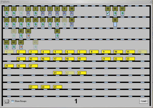
A powerful feature of the cell control software is its scheduling flexibility. According to Mr. Scoffield, this flexibility is essential to his concept of deploying rapid-response manufacturing to meet short customer-order delivery dates. This flexibility is manifested in the operator interface and its drag-and-drop operation. This means that the operator can view the entire layout of the cell as represented by graphic icons of each machine, the storage racks, the robot and the material infeed/takeout station. Clicking on one of these graphic elements brings up an enlarged “picture” of current pallet and basket assignments along with the queue of jobs prioritized for execution. To change the job queue, the operator clicks on the job icon and uses the cursor control device to drag the icon to a new position in the queue. Releasing the icon “drops” the job there, and the system automatically resets the order in which that job will be executed. The operator uses a similar drag-and-drop procedure to scan the rack of stored baskets and the pallets. By selecting the icon of a basket or pallet and moving it to the infeed/takeout station, the operator sends commands to the robot. As soon as it is free, it follows the commands to deliver the requested items.
The flexibility of this drag-and-drop scheduling system is important. That is because it allows Mr. Scoffield and his staff to make last-minute adjustments to the work schedule and accommodate incoming orders almost instantly. It also allows the shop to line up jobs that will run overnight or during a weekend. The number of pallets and baskets in the system is adequate to occupy the cell with about 3 days of unattended operation.
Thinking Ahead
Big Sky’s Phase II cell has room for 12 wire machines, although only seven are in place right now. Mr. Scoffield opted for a cell that could be easily expanded because he was thinking ahead to the future growth of his company. New machines can be added to increase the cell’s capacity to produce either PCD/CBN segments or the cutters with tips brazed in place. Of course, the fact that the future is never entirely predictable also occurred to him.
This was another reason for investing in flexible automation. Customer demand was strong when he placed the order for the cell, but business dropped off significantly a few months later with the economic downturn. Nevertheless, Mr. Scoffield reports that the cell has been running at least two full shifts a day, seven days a week since it went into full operation, despite the recession. The shop has been able to adjust elsewhere by reducing staff hours, yet the automated production system has been able to maintain the shop’s record for reliable, on-time order fulfillment.
With an economic recovery seemingly on the way, Mr. Scoffield expects the rotary cutting tools to be the portion of his business to pick up the most. That means the next machine likely to be added to the cell will have the additional fifth axis and probing system installed for this work.
In the meantime, he hopes his example of cellular manufacturing will inspire other shops to consider automation.


Related Content

Buying a Lathe: The Basics
Lathes represent some of the oldest machining technology, but it’s still helpful to remember the basics when considering the purchase of a new turning machine.
Read More
How to Reduce Cycle Times by 70% and More on Your Existing CNCs and Dramatically Improve Tool Life Too
By employing advanced high efficiency milling techniques for the entire machining routine, SolidCAM’s iMachining technology can drastically reduce cycle times while vastly improving tool life compared to traditional milling.
Read More
Grinding Wheel Safety: Respect The Maximum Speed
One potential source of serious injury in grinding comes from an oversight that is easy to make: operating the wheel in an over-speed condition.
Read More
Understanding Swiss-Type Machining
Once seen as a specialty machine tool, the CNC Swiss-type is increasingly being used in shops that are full of more conventional CNC machines. For the newcomer to Swiss-type machining, here is what the learning curve is like.
Read MoreRead Next

3 Mistakes That Cause CNC Programs to Fail
Despite enhancements to manufacturing technology, there are still issues today that can cause programs to fail. These failures can cause lost time, scrapped parts, damaged machines and even injured operators.
Read More

The Cut Scene: The Finer Details of Large-Format Machining
Small details and features can have an outsized impact on large parts, such as Barbco’s collapsible utility drill head.
Read More