
Break The Accuracy Barrier
"Reference comparison" uses probing to hold accuracies tighter than inherent process error.
Share


Phillips Corporation - Education
Featured Content
View More


Phillips Corporation
Featured Content
View More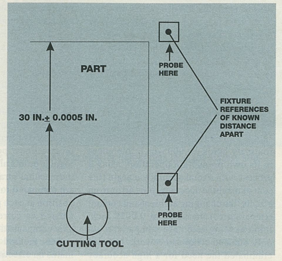
Fig. 1 - Normal machine and process errors may make it impossible to hold the 30-inch dimension to the given tolerance, using just a straight-line move between the two surfaces. A more accurate method is reference comparison, where CNC probes references of known position to update its position prior to a critical move.
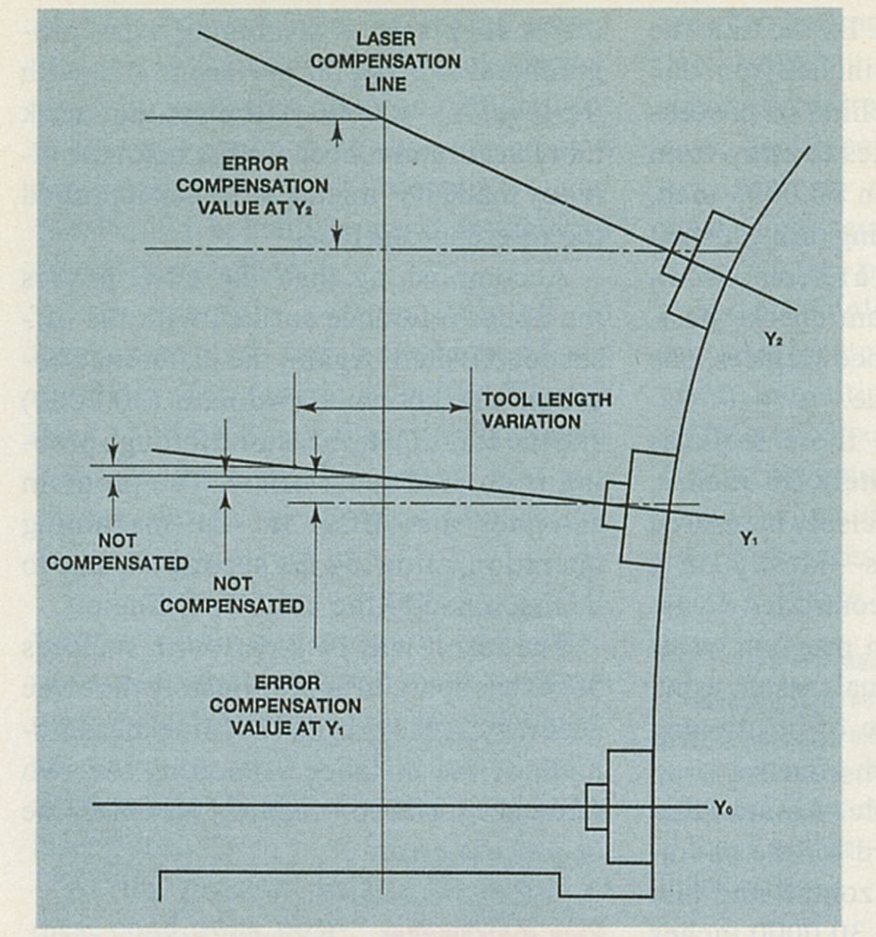
Fig. 2 - When the Y axis is bowed so that pitch error increases as the spindle rises, laser compensation ''corrects'' the pitch error only when tool length matches the length from laser optic to the nose of the spindle.
Fig. 3 - Despite a squareness error of 0.00004 inch in X for every 1 inch in Y away from the line of laser compensation, the machine above can position the three bores correctly through reference comparison. The reference is the surface at X = 16, probed at the level of each bore immediately before machining.
.gif)
Here is the precision link part, along with the references used to locate the two bores to within ±0.0005 inch of one another. Though there are two small reference blocks (detailed in the next photo), they are bolted to a long connecting bar, to give the entire assembly a set of thermal expansion characteristics similar to that of the link part itself.
.gif)
Here is one of the small reference blocks used in the precision link part machining.
To overcome spindle drift error in opposing bores machined through B-axis indexing, reference surfaces are placed in front of the bores, along the common center line.
The spindle-mounted probe as a tool for in-process error compensation may be difficult to imagine. Probing is generally used as a productivity tool, to let the CNC locate a feature automatically, instead of having an operator locate it by hand. However, when the position of the feature probed is known already, probing becomes an accuracy tool. It can let a machining process beat its own inherent error, to hold tolerances tighter than its accuracy margin would otherwise allow.
The technique, called reference comparison, involves employing a reference object close to the workpiece as an objective measure of positioning error.


Here's the idea: Just prior to making a critical machining pass, the CNC probes the reference. Comparing its own "sense" of position to the known position of this surface--which is precisely determined prior to machining--lets the CNC measure its own error. It programs a temporary offset equal to the discrepancy. By adding this offset to the critical machining move, the CNC edits the measured error out of the process. Reference comparison assumes that the error in the probing move and the critical pass is nearly the same--which it should be, if reference and workpiece are close to one another and physically similar. If true, then the critical pass will come in on target, despite whatever error accumulated in the moves to load the tool and return to the part.
Cincinnati Machine [now Fives Cincinnati --ed.] has demonstrated the effectiveness of this technique. Using its own patented version of reference comparison, Cincinnati Machine routinely holds ±0.0005-inch tolerances in its own production operation, using a process with a total accuracy margin (the sum of machine accuracy, plus error from effects like changing ambient and coolant temperatures) measured at 0.0028 inch. Implementing reference comparison not only reduced scrap and rework, but also eliminated the need for a high accuracy boring mill for one of the company's critical parts.
Andy Haggerty, Cincinnati Machine emeritus R&D engineer, has studied probing for nearly 20 years. He was instrumental in developing Cincinnati Machine's reference comparison approach. This article summarizes his insights into the technique, and his advice for other shops hoping to apply it to their own high precision parts.
Where The Laser Leaves Off
Compensating for error instead of correcting it has been popular almost since the dawn of NC. No one gets dirty hands that way. But a more important reason is that many machining center errors are either untraceable, or impractical to fix for any number of other reasons.
Early error compensation took the form of "funny tapes"--programs adjusted to individual machine tools, employing lopsided positioning commands to make up for errors consistently observed on a given machine. Though this approach often did improve the process, it is employed less and less in an age when distributed numerical control and flexible cells require programs to be accessible to multiple CNCs, and multiple machines.
A more effective technique is linear error compensation using a laser measurement system. The laser system--often directly interfaced to the CNC--takes precise linear position measurements at regular points along one or more lines of the machine's travel. These measurements are compared to the CNC's programmed position at each point, with discrepancies entered as correction offsets in a CNC axis compensation table.
This method of laser calibration remains an effective technique for improving the accuracy of a machining center across its work zone. Reference comparison can't replace it, but can complement it. While a common misconception says that laser calibration "corrects" a machine tool, it actually leaves many sources of error untouched.
For example, errors related to squareness and angular effects of the machine axes remain after the laser is done. And off-line calibration is powerless to address machine errors that will change during the process, due to the changing temperatures. In fact, machine positioning is truly "correct" only for moves at slide positions and machine component temperatures matching those of the laser compensation move, using a tool length equal to the distance from the spindle nose to the laser optic.
As the process departs from any of these conditions, positioning error increases, leaving room to improve the process through reference comparison.
The Basics
A machining program using reference comparison doesn't trust the program coordinates to locate the tool point accurately enough for critical machining. Instead, it references each critical machining pass to a reference surface with a known location.
This reference surface can be a pre-machined feature of the part itself, but can also be a feature of a separate reference object. In the latter case, the object is positioned on the fixture prior to machining, using precise measuring equipment to locate it with respect to the position of the part. Often, programs employ multiple reference surfaces to locate a machined feature precisely in multiple axes.
Reference comparison recognizes that errors accumulate over long machine moves. Consider the part in Figure 1, which requires opposing machined surfaces to locate 30 inches apart in Y, to an accuracy of ±0.0005 inch. By the time the CNC moves the slides 30 inches from one surface to the other, machine or process errors might cause the axes to stray from this position by more than ±0.0005 inch. Therefore, instead of relying on a constant set of program coordinates, a reference comparison machining program checks positioning against two reference surfaces, one near each machined surface.
The distance between these surfaces need only be approximately 30 inches, but its true distance is precisely measured before machining begins--ideally on a CMM in a temperature-controlled room. The reference comparison program treats this distance as a dimensional master, using it to update its own sense of positioning through the use of program offsets.
The procedure is simple. Assume that the machining center used for the operation in Figure 1 is a horizontal, and that the references are indeed 30.0000 inches apart. The program would then be written to include offsets that assign coordinates to the two surfaces that are separated by the same distance--say, Y = 0.0000 and Y = 30.0000.
The program begins by probing the lower reference surface. Because of the influence of machine or process error, the program coordinates may show the surface to lie at Y = -0.0003, Y = 0.0001 or some other slightly inaccurate coordinate. However, the reference has already been positioned at Y = 0.0000, so the program is justified in adjusting the coordinates to match this value. It does this by subtracting the coordinate measured through probing from the known coordinate and storing the difference as an offset.
This offset is activated when the machine loads the milling cutter. With the offset in place, a machining pass programmed to bring the surface in line with the level Y = 0.0000 will meet that mark more accurately, because the machine already made its "mistakes" when it probed the reference surface.
Accomplishing that, the CNC probes the upper reference surface with the offset deactivated. Again, the difference between the known coordinate (30.0000) and the coordinate measured through probing is entered as an offset. The program activates this offset for the machining operation, allowing the second surface to be machined to the same coordinate.
The result will be a part with surfaces 30 inches apart, to approximately the same accuracy as the original off-line measurement of the distance separating the two reference surfaces-regardless of machine or process error.
Play Matchmaker
Reference comparison can improve on the machining accuracy achieved through laser compensation for one reason: It lets the process avoid the errors that still remain after laser compensation is complete. These can include tool tip, axis squareness and thermal errors.
Maximizing the accuracy gains from reference comparison means minimizing the chance for errors such as these to creep in between the probing and machining moves. This is a three-step process:
1. Match probe length and tool length to overcome tool tip error.
Several geometric errors-including X yaw, Y pitch, X and Y roll, and X-Y axis out-of-squareness-can place the tip of the tool in a position different from what the X and Y scale coordinates indicate. When such an error does exist, its magnitude is a function of tool length. Laser compensation "corrects" tool positioning only when tool length is the same as the distance from the laser optic to the spindle nose. Figure 2 shows why.
The horizontal machine in the figure has a not-uncommon condition: a "bowed" Y-axis (exaggerated in the illustration), causing the Y-axis pitch to increase as the spindle travels up. The result is a tool tip that rises somewhat faster in Y than does the Y-axis slide.
Even limiting the process to tools that match the optic-to-spindle length fails to solve the problem. Pitch error changes with changing temperature (the concern of point 3, below), so not only tool length, but also the machine element temperatures would have to be tightly controlled.
A better solution is just to avoid the error, by matching the length of the probe to the tool length of the critical machining pass. The tool tip error is then identical for both, making this error just one more component of the total error compensated by the reference comparison offset.
The magnitude of tool tip errors is generally small enough that the match between tool and probe lengths doesn't have to be precise. Agreement of ±1 inch is sufficient--a match that can probably be achieved solely through the choice of the probe's stylus from within a standard kit.
2. Match axis coordinates to overcome squareness error.
Another source of inherent machine error is an out-of-square condition between the X and Y axes. The magnitude of this error grows as the machine travels away from the line of travel along which it was laser compensated. The error can be the result of out-of-square machine axes, or a part or fixture mounted out-of-square with respect to the machine.
To address this problem using reference comparison, the probing move and the machining move should have similar coordinates in as many axes as possible. The separation should be no more than 5 inches, but identical coordinates are even better. If the machine is spared from moving in a given axis, it's also spared from accumulating squareness error.
Figure 3 illustrates how the lack of X-Y squareness affects accuracy. The part shown requires three holes to be bored along the line X = 20.0000, at Y = 5.0000, 15.0000 and 25.0000. The right face of the part corresponds to the line X = 16.0000. Though the machine has been laser compensated at the level Y = 15.0000, a small squareness error translates to 0.00004 inch of deviation in X for every 1 inch of movement away from this value in the Y axis.
Given the squareness error, a cycle that bored all three holes using the same set of program coordinates could accurately position only the hole at Y = 15.0000. The upper and lower holes would position incorrectly in X, by -0.0004 inch and +0.0004 inch, respectively.
However, because the distance of each bore from the right face of the part is precisely defined--4.0000 inches--both the upper and lower bore can be positioned accurately, in spite of the squareness error, by using this reference.
The reference comparison portion of the cycle would probe this face three times immediately before boring--once at the Y-axis position of each cut. (Even the middle hole is probed. In an actual process, setup- or process-related errors could cause the surface to locate incorrectly at this level, too--and the extra probing pass would add little to cycle time in this instance.)
For example, to position the lower hole, the CNC would probe the right face along the level Y = 5.0000. However, because of the squareness error, it would meet the surface 0.0004 inch sooner than expected. To correct for this, the program would enter an offset value to be added to the X-axis coordinate of the machining pass--in this case, -0.0004. The same steps would be repeated at Y = 15.0000 and Y = 25.0000 to position the other two bores. A similar degree of inaccuracy may result from an angular error along the Z axis. To overcome this error, the probing pass would be made at a slide position in Z approximating that of the machining pass-for example, at the midpoint of the boring move. Note that this is slide position, not Z-axis tool-tip position. However, following the recommendation to match tool length to probe length (above) will automatically make slide and tool tip positions the same.
3. Match materials and machine soon to overcome thermal error.
Machine tool straightness, squareness and angular errors are generally dynamic. They change over time, as thermal effects distort machine elements, and change their positions relative to one another. Even on a "perfect" machine, thermal effects would still affect the process, as changing temperature caused the part and setup to change position relative to the machine.
Thermal effects are the most important reason to resort to reference comparison. If error never changed, then permanent offsets could adjust for them and in-process compensation would be unnecessary. However, precision machinists know that a real process is always in a state thermal and geometric flux.
Flood coolant can improve thermal stability, but only partially. Unless a coolant temperature control system is used, applying flood coolant just introduces changing coolant temperature as another thermal effect. And coolant temperature can at times vary significantly throughout the machining run.
Avoiding thermal errors through reference comparison takes a two-part strategy: (1) Choose the reference object to have thermal expansion characteristics similar to the part, and (2) perform the critical machining as soon as possible after the reference probing move, leaving little time for temperature to change.
The reference object material should be the same alloy as the workpiece, in the same metallurgical condition. The object geometry should also be chosen to produce a thermal expansion response closely matching that of the workpiece. This means similar orientation, as well as similar length and cross-section-or more precisely, a similar ratio of volume to surface area.
But even if the dimensions of the workpiece and reference object are changing identically, they are still changing. In most processes, this means data measured through probing become increasingly less accurate with each minute that passes. For this reason, the critical machining pass should be performed immediately after the probing pass used to locate it. No other machining operations should separate the two.
Return On Investment
The costs of reference comparison are obvious. The technique adds time and complexity not only to the machining cycle, but also to setup. It's not for every part-not even for every precision part. However, the technique has proven itself a profitable tool to Cincinnati Machine, and several other high precision manufacturers.
When reference comparison tightens the tolerance band that a machine can reliably hold, it can improve the process by reducing scrap, and eliminating the extra transport and setup costs associated with high precision operations on separate machines. The "cost" in setup and cycle time then becomes an investment-one that pays its dividends downstream. MMS
Sidebar 1: Precision Link Example
A cast iron link used in toggle mechanisms of injection molding machines features two 2-inch diameter bores whose center-to-center distance of 26.380 inches must be accurate to within ±0.0005 inch. Though holding this tolerance used to require a manual boring mill, reference comparison now allows Cincinnati Machine to bore the holes accurately on a CNC machining center--as part of a process with an accuracy margin measured at 0.0028 inch.
Because the part is cast, no surface of the part itself can be trusted as a reference for the bores. Therefore,Cincinnati Machine uses a cast iron mounting plate set adjacent and parallel to the part, supporting two reference blocks positioned so that their Y reference surfaces are 27.500 inches apart.
Each block provides ground and hardened reference surfaces which the CNC probes in X and Y, to counter the effects of any axis positioning errors immediately before the bores are machined. The blocks are positioned repeatably on the mounting plate using two locator pin holes. Both blocks are probed after the holes have been rough-bored, to locate the holes for finish machining.
Sidebar 2: Opposing Bores
Reference comparison can also be used to correct errors associated with workpiece rotation--whether manual, or through B-axis indexing.
An example is a part with opposing bores that must share a common center line. Though the ideal way to ensure this concentricity would be to bore straight through in a single operation, the part does not leave enough room within the machine's work zone to accommodate such a long boring bar. The part must instead be rotated.
However, the spindle in this example has a drift error of +0.0020 inch with respect to the pallet's center of rotation. Even with perfect concentricity between the coordinate axes and pallet rotation, this error would still cause the bore center lines to differ by 0.0040 inch--the combined effect of the displacement of the near hole by +0.0020 inch, and the far hole by -0.0020 inch.
The solution is to place reference surfaces along the bores' shared center line, on each side, and to probe these surfaces to locate each bore immediately before machining. This not only eliminates the influence of the spindle drift, but can also compensate for the part being positioned off-center with respect to the axis of rotation of a B-axis move.
Sidebar 3: Probing Fundamentals
Pay attention to technique to win the most benefit from probing, says Cincinnati Machine's Andy Haggerty. No matter how probing is used--whether for reference comparison, or just to locate a surface prior to machining--these tips apply:
1. Use the same approach direction for probe and tool. When the coordinates of a machining pass are based on data gathered through probing, have the machine move in the same direction to position the tool that it did to position the probe.
2. On a horizontal, position tool and probe up in Y. That is, against gravity. This also reduces lost motion error, by tending to compress the axis ballscrew.
3. Recalibrate daily. Recalibrate also after adjustment or alteration of the probe, particularly a stylus change.
4. Clean surfaces first. Even a speck of dirt added to a probing measurement will result in out-of-tolerance parts in precision machining operations. Cleaning can be automatic, via a programmed coolant wash. If this doesn't remove all chips and debris, consider a dwell cycle in the program, to give the operator time to clean the part by hand.
5. Average three hits to reduce repeatability error. Consider replacing a standard "touch and go" probe move with a routine for probing the same spot three times and taking the average. This reduces random repeatability error.


Related Content

MAG Automotive HMC Provides Precise, Reliable Performance
MAG Automotive’s Specht 500 NG HMC is designed and built in Detroit for demanding production environments.
Read More
SW North America Open House Showcases Advanced Machining Solutions
SW North America hosts its 2025 Open House at its Michigan headquarters, featuring live demonstrations of the BA 322i and BA Space3 machining centers with a focus on medical and aerospace applications.
Read More
Mazak Achieves Production Milestone, Announces Plans to Open New Technical Center
Mazak Corporation celebrates the completion of its 40,000th machine at the Mazak iSmart Factory in Florence, Kentucky, showcasing advanced manufacturing and digital integration.
Read More
DN Solutions America Unveils Impressive Chicago Technical Center at IMTS 2024
New tech center is serving as a cutting-edge showroom and a technological hub for advanced machining applications.
Read MoreRead Next

WEBINAR: From Machine Data to Guided Action: How Modern Shops Are Closing the Execution Gap
In this webinar, MachineMetrics Product Manager Josh Fish is joined by Pindel Global Precision's Thomas Deslongchamps, for a candid look at what closing the execution gap actually looks like inside a precision machining shop.
Read More