
Minimizing Vibration Tendencies In Machining
Precision internal machining operations are now carried out almost exclusively using hard-metal or diamond tipped cutting tools. Tool holders are available in a variety of forms to suit the specific machining requirements. The material properties of the toolholder have a large influence on both the surface quality and dimensional accuracy of the machined component (workpiece), and on the life of the cutting tool. This becomes critical when machining deep holes, because it is necessary to use a tool with large length to diameter (L/D) ratio or overhang.
Share


Phillips Corporation - Education
Featured Content
View More


Phillips Corporation
Featured Content
View More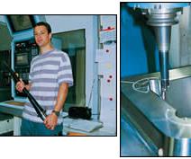
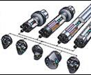
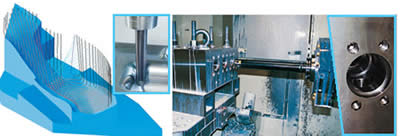
The modular 570 tooling system uses various cutting heads on various boring bars, including damped bars.
By the use of passive damping elements, integrated in the boring bars, the dynamic behavior of the tools can be optomized.

Specifically engineered damped boring bars have been the solution to many demanding applications involving contoured holes.
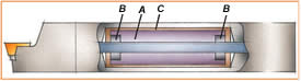
The main parts of the damped boring bar are: a)heavy turning body, b) rubber brushes c) special oily liquid
With an overhang of more than 4 times the tool diameter, vibration tendencies can become more apparent and damped tools come into the picture as a good solution.With a damped pre-tuned boring bar machining of holes with a depth of up to 14 times the diameter of the bar can be performed with good results.
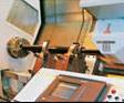
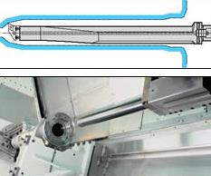
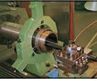
Damped boring bars are applied in most modern machine tools such as millturn machines (top) and machining centers (below)
Vibrations in the cutting process causes alternatives in the structure and forces.
Seen as a whole, the machine, cutting tool, and workpiece from a standard system having complicated dynamic characteristics.
Precision internal machining operations are now carried out almost exclusively using hard-metal or diamond tipped cutting tools. Tool holders are available in a variety of forms to suit the specific machining requirements. The material properties of the toolholder have a large influence on both the surface quality and dimensional accuracy of the machined component (workpiece), and on the life of the cutting tool. This becomes critical when machining deep holes, because it is necessary to use a tool with large length to diameter (L/D) ratio or overhang. A high degree of overhang, together with the material properties of the workpiece and various other factors, can lead to excessive vibrations in the tool shaft, which in turn causes undesirable chattering. By the use of passive damping elements, integrated in the tool shaft, the dynamic behavior of the tool can be optimized.
INTRODUCTION TO VIBRATIONS
The development within production engineering is accompanied by increasing quality requirements of the produced workpieces. In addition to the product-related high-quality features such as the shape, dimensional tolerances and surface qualities, the effectiveness and controllability of the manufacturing process are relevant factors. As a result of intense development work of the cutting edge, the capability of the cutting tools has been increased considerably.


Seen as a whole, the machine, cutting tool, and workpiece form a structural system having complicated dynamic characteristics. Under certain conditions vibrations of the structural system may occur, and as with all types of machinery, these vibrations may be divided into three basic types:
Free or transient vibrations: resulting from impulses transferred to the structure through its foundation, from rapid reversals of reciprocating masses, such as machining tables, or from the initial engagement of cutting tools. The structure is deflected and oscillates in its natural modes of vibration until the damping present in the structure causes the motion to die away.
Forced vibrations: resulting from periodic forces within the system, such as unbalanced rotating masses or the intermittent engagement of multitooth cutters (milling), or transmitted through the foundations from nearby machinery. The machine tool will oscillate at the forcing frequency, and if this frequency corresponds to one of the natural frequencies of the structure, the machine will resonate in the corresponding natural mode of vibration.
Self-excited vibrations: usually resulting from a dynamic instability of the cutting process. This phenomenon is commonly referred to as machine tool chatter (chatter vibrations) and, typically, if large tool-work engagements are attempted, oscillations suddenly buildup in the structure, effectively limiting metal removal rates.The structure again oscillates in one of its natural modes of vibration.
It is important to limit vibrations of the machine tool structure as their presence results in poor surface finish, cutting edge damage, and irritating noise.The causes and control of free and forced vibrations are generally well understood and the sources of vibration can be removed or avoided during operation of the machine. Chatter vibrations are less easily controlled and metal removal rates are frequently limited because the operator must stop the machine to improve the machining conditions, which often means reducing the depth of cut or feed rate.This article deals with chatter vibrations and how these disturbances can be minimized by the use of damped tools.
CHATTER VIBRATIONS AND DAMPING
The basic cause of chatter is the dynamic interaction of the cutting process and the machine tool structure. During cutting, a force is generated between the tool and workpiece, which acts at an angle to the surface.The magnitude of this cutting force depends largely on the tool-work engagement and depth of cut. The cutting force strains the structure elastically and can cause a relative displacement of the tool and workpiece, which alters the tool-work engagement (undeformed chip thickness). A disturbance in the cutting process (e.g., because of a hard spot in the work material) will cause a deflection of the structure, which may alter the undeformed chip thickness, in turn altering the cutting force. There is a possibility for the initial vibration to be self-sustaining (unstable) and build up, with the machine oscillating in one of its natural modes of vibration.
To make the increased capability of modern cutting edges, the cutting-tool materials available, powerful and stable machine tools, holding tools and cutting tools are required. The shape accuracy of the produced parts is determined by the kinematic machine tool behavior and the static, dynamic and thermal stiffness of the machine tool system. The surface quality that can be achieved depends on the geometry of the cutting edge, the machining parameters and the dynamic behavior of the system: machine tool - cutting tool - workpiece. The metal removing capacity that can be achieved without chatter vibrations is clearly defined by the dynamic machine tool behavior.
For machining complex shapes of dies and moulds, usually tools with a long overhang are used. Equally the machining of the integral components of aircrafts and cars requires the use of tools with a large length to diameter (L/D) ratio. Also for the machining of boreholes and for the inside machining of cylindrical workpieces long boring bars are required.
With increased overhang the tool can become the deciding weak link in the system of machine tool - cutting tool - workpiece. Furthermore, the low static stiffness and material damping characteristics of metallic materials also causes a high dynamic compliance. This can lead to instability of the chip removal process and chatter vibrations.
POOR MACHINING RESULTS ...
... are usually derived from chatter vibrations in machining, with cutting tool damage and unsatisfactory workpiece quality. In order to achieve sufficient process stability, the metal removing rate should be reduced or the cutting tool geometry changed. Material substitution as well as geometric shape optimization leads to increased dynamic stability of boring bars. By the use of passive damping elements, integrated in the boring bars, the dynamic behavior of the tools can be optimized.
Generally, machining up to four times the diameter of boring bars does not cause any problems from the vibration point of view, provided that correct conditions apply as regards cutting data and inserts.
There are three different types of damped bars, depending on the length of overhang. Standard bars with a short damping system for machining up to 7 times the bar diameter, standard long bars for machining up to 10 times the bar diameter and cemented carbide reinforced bars (CR bars) for machining up to 14 times the bar diameter.
CEMENTED CARBIDE BORING BARS ...
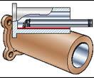
... made of sintered tungsten carbide or machinable sintered tungsten alloys are an excessively costly solution. In case of a tool collision, a solid carbide bar will snap off in one or more pieces, often with fragments going like projectiles out of the machine tool. Carbide reinforced (CR) bars have some advantages compared to solid carbide bars. A CR-bar is an assembly of carbide rings or sleeves held together by compressive stress from a steel tension bar going through the center of the sleeves. In case of a collision, this will stress the steel parts beyond material yield limit and it will bend away. In a worst case scenario, one or two of the carbide sleeves are also damaged, but these can be replaced at a relatively low price, and the bar can be repaired for a total price which is far less than that of a replacement.
STRETCHING LIMITS WITH EXISTING TOOLS
Stability is critical for any machining operation.Vibrations can often be avoided by choosing the right insert, the best standard tool holders, and the right cutting data. An essential part of the service provided by Sandvik Coromant and Teeness, is assisting customers in the application of tools, providing information and training of personnel.
Generally, a solid boring bar will perform adequately in general turning out to 4 times its diameter without vibrations. But in more demanding applications, such as internal threading and grooving, vibrations may start at an overhang between 2 and 3 times the bar diameter. In comparison, the most highly developed bars stretch 15 times beyond their own diameter. Some information on how limits may be stretched using existing tools follows.
A vibration is a variable deflection, thus, no defection means no vibration. Vibrations in a cutting tool are triggered and maintained by a dynamic cutting force. Even in a continuous cut, the cutting force will have small rapid changes in both size and direction around a certain average. The keys to eliminate vibrations are the following: Increase static stiffness, reduce cutting forces, and increase dynamic stiffness.
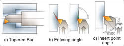
To increase static stiffness, choose the largest possible diameter for the boring bar and the minimum length. Special bars can also be shape-optimized, for instance be made tapered or elliptic, to utilize all available space in the workpiece. Bars can also be reinforced with materials that are stiffer than steel.
An increased length from 4 to 10 times the bar diameter will give a 16 times larger deflection for a bar taking a constant cutting force.A further extension from 10 to 12 times the bar diameter, gives another 70% increase in deflection from the same cutting force. Holding the bar length constant while changing the bar diameter from 25 to 32 mm, reduces deflection with 62% for equal cutting forces. It is important to cut with sharp edges to minimize the cutting force required to perform the machining operation - a positive cutting geometry reduces cutting forces.
An entering angle close to 90° will direct a maximized feed force in the axial direction of the bar. However, this is not effective unless the nose radius is smaller than the radial depth of the cut. If there is no vibration in the radial direction the boring bar will make a good surface even with small vibrations in the tangential direction.
The smallest acceptable insert point angle will give good clearance of a trailing surface, and small chip area variations if the tool starts vibrating in a radial direction. Reduced weight of cutting units will minimize the kinetic energy in a possible vibration. This will make it easier for the tool to damp possible vibrations, and thus stretch the maximum overhang for both solid and damped tools.
For some machining applications, the above given guidelines are not enough to sufficiently reduce vibration tendencies. These are in many cases regarded as impossible operations, with damped tools being the only option. The choice can sometimes lie between using damped tools or turning away the work, the latter course usually being unthinkable. In addition to better productivity, better surface finish, increased tool-life and better tolerances, the ever increasing higher environmental demands being set in machine shops also creates work for damped tools. Vibration from machining creates noise and sometimes it is necessary to use damped tools to keep within the maximum noise level permitted in a workshop.
The use of damped tools was in the past considered to be exotic and complicated, but this is not the case today. The most critical issue in manufacturing is to perform machining operations in the most efficient way. Today`s damped tooling includes tools that are pre-tuned to the correct frequency in relation to the tool length that is ordered, requiring basically for the damped boring bar and machine to be set up as you would with a conventional, solid boring bar.
STATE-OF-THE-ART IN DAMPING
Several techniques are known for enhancing dynamic stiffness and stability (chatter-resistance) of long cutting tools and, thus, increasing allowable overhang. The four most widely used and most universal approaches are:
- Use of anisotropic bars with specifically assigned orientations of the stiffness axes
- Use of Young’s modulus and/or high damping materials
- Use of passive dynamic vibration absorbers (DVA)
- Use of active vibration control means
The use of anisotropic bars is based on a theory explaining the development of chatter vibrations during cutting by an intermodal coupling in the two-degrees-of-freedom system referred to the plane orthogonal to the bar axis and passing through the cutting zone. According to this theory there is a specific orientation of stiffness axes relative to the cutting forces, resulting in a significant increase in dynamic stability.
The most frequently used high Young’s modulus materials are sintered tungsten carbide, and machinable sintered tungsten alloy with an added 2-4% of copper and nickel. Both materials are expensive. Solid bars made of both these materials allow stable cutting with ratios L/D < 7.
At present, the commonest approach to enhancing the dynamic stability of long bars is the application of passive dynamic vibration absorbers (DVA) with an inertia mass (pre-tuned bars). The effectiveness of a DVA for a given mass depends on the vibration amplitude at its attachment point. Accordingly, absorbers are usually installed at the furthest available position along the bar. Another factor determining their effectiveness is the mass value of the inertia weight of the DVA. In boring bars, the DVA has to be placed inside the structure. This limits both the position of the DVA along the bar axis and the size of the inertia weight, which has to be positioned in an internal cavity whose diameter must be much smaller than the bar diameter. To achieve a reasonable degree of DVA effectiveness, materials with very high specific density must be used for inertia weights.
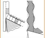
THE PRE-TUNING SYSTEM ...
... of the bar consists mainly of a heavy tuning body (A) suspended in two rubber bushes (B), on at each end of the tuning body. The tuning body is then surrounded by a special oily liquid (C).
If harmonic oscillation (vibration) tendencies should arise during the machining process, the tuning system will immediately come into force, and the kinetic energy of the bar will be absorbed in the tuning system. As a result, vibration is minimized and cutting conditions optimized. It is quite feasible to machine components that require a tool overhang of more than 10 times the tool diameter. Furthermore, with cemented carbide reinforced special bars, overhangs of 14 times the tool diameter can be dealt with successfully.
ACTIVE VIBRATION DAMPERS ...
... are effective, but require vibration sensors and actuators generating forces opposing the deflections of the tool during the vibratory process. The most frequently used are active systems with cavities in the mandrel (bar) body, which are filled with pressurized oil. Pressure values in the cavities vary according to the output of the control system, thus generating dynamic deformations to cancel the chatter vibrations. Present design of active dampers is not very reliable in the shop environment, and may require frequent adjustment.The ultimate L/D ratio for a boring bar with an active damper is 10 – 12.
EXPERIMENTAL WORK
The experimental work is a comparative study of the metal removal rate for different types of boring bars at varying L/D ratios performed at SINTEF. Long and slender boring bars for single-point turning are particularly susceptible to self induced vibration. The productivity is traditionally low when using these types of tools.This study includes machining tests with conventional and damped boring bars of steel and tungsten alloy.
With internal tooling the problem of instability is a result of the machining. The only cutting force component which does not need to be counteracted with support is the axial force (Ff) which is directed along the axis of rotation, along the shank of the working bar. The radial cutting force (Fp) bends the tool out and away from the cutting zone in such a way that the diameter of the hole is affected.The tangential cutting force (Fc) bends the tool downwards and away from the center line along which the tool is designed to cut. Poor surface finish is the first sign that the cutting force is not being sufficiently damped.
Five different boring bars were tested, all with a diameter of 25 mm.The length to diameter (L/D) ratio ranges from 3 to 14.
All the damped boring bars are Sandvik Coromant 570 style produced by Teeness, strong and compact with coolant through center. These bars features the best anti-vibration performance due to minimum weight in front, given by the short distance from the insert tip to damper. The damping system is based on use of passive dynamic absorbers.
In order to minimize the effect of the tool wear on surface roughness and process stability, the inserts were slightly worn by machining 3 min before testing. Each insert was used for maximum 6 min. The depth of cut was corrected for deflection of the boring bars.The surface roughness was measured according to ISO 4288:1998. Two tests were carried out.
TEST A
A comparative study of workpiece surface roughness for different types of boring bars at varying L/D ratio. The test was performed as a finishing operation with one kind of inserts and appurtenant cutting data.
TEST B
A comparative study of metal removal rate (productivity) for different types of boring bars at varying L/D ratio. The tests were performed at a constant depth-of-cut to feed ratio. The surface roughness constraint was Ra = 3.6 µm.
RESULTS
The results are shown in the accompanying two diagrams. Conventional boring bars can be used up to L/D 4 for the particular set of cutting data.
Damped boring bars can be used up to L/D 13. However, each damped bar has a restricted working area regarding the L/D ratio. It is also shown that the metal removal rate can be sustained up to L/D 12.
CONCLUSION
The least rigid components of machining systems are long and slender (cantilever) tools and cantilever structural units of machine tools (rams, spindle, sleeves, etc.). These components limit machining regimes due to the development of chatter vibrations, limit tool life due to extensive wear of cutting inserts, and limit geometric accuracy due to large deflections under cutting forces. Use of materials having a high Young’s modulus (such as cemented carbides) to enhance the dynamic quality of cantilever components has only a limited effect and may be costly.
The use of passive vibration absorbers combine exceptionally high dynamic stability and performance characteristics with cost effectiveness.The performance and interaction of these tools were validated by extensive cutting tests with damped boring bars from Teeness. Stable performance with length-to diameter ratios up to L/D = 13 were demonstrated. Comparative tests with similar, commercially available bars from Sandvik Coromant demonstrated the advantages with boring bars featuring passive vibration absorbers, both in surface conditions and productivity.
TEENESS – A SANDVIK COROMANT PARTNER
Teeness is a modern tool manufacturer with 70 employees. Their knowledge about basic metal cutting and mechanical vibrations have made them Sandvik Coromant’s specialist partner on machining with minimized vibration tendencies. The Teeness office and factory are situated two kilometers west of downtown Trondheim, the third largest city in Norway. All anti-vibration tool adapters from Sandvik Coromant are manufactured at Teeness in Trondheim,Norway. Teeness also manufactures supporting products such as solid adapters and cutting heads for internal turning. Teeness manufactures hundreds of standard Sandvik Coromant products. As partners, the companies team up to support metalworking industries to provide the best solutions.
Demanding applications may require special solutions. Each year Teeness manufactures more than 250 engineered special tools according to specifications from customers around the world.As each one of these makes an impossible operation possible,Together, Sandvik Coromant and Teeness offers customers unique manufacturing advantages.
SINTEF
SINTEF, the Foundation for Scientific and Industrial Research at the Norwegian Institute of Technology, is the largest independent research organization in Scandinavia. SINTEF has 1700 employees and the turnover in 2001 was 232 million Euro. Contracts for industry and the public sector generated more than 90% of this income, while 7% came in the form of basic grants from the Research Council of Norway. SINTEF sells research-based knowledge and related services to Norwegian and international clients. SINTEF collaborates closely with the Norwegian University of Science and Technology (NTNU) and the University of Oslo. Personnel from NTNU work on SINTEF projects, while SINTEF staff teaches at NTNU.The SINTEF-NTNU community involves the widespread joint use of laboratories and equipment. SINTEF is committed to produce high quality deliverables.This means that the products are to be relevant and useful for the clients, maintain high scientific and quality standards, and be presented professionally. If required by clients, SINTEF’s quality assurance ensures that the projects meet the requirements of NS-EN ISO 9001 quality standards. Most of the laboratories are accredited according to EN 45001 or the GLP scheme.


Read Next

Modern Machine Shop’s 2026 Top Shops Benchmarking Survey Goes Live Feb. 1
Modern Machine Shop is proud to announce the 2026 Top Shops Benchmarking Survey, opening February 1 through March 31, 2026.
Read More