The Online Optimizer
Coming soon: The Machine Tool Genome Project promises to let almost any machine shop use its machining centers more productively. Shops will benefit from tap-test findings without personally tapping any of their own machines or tools.

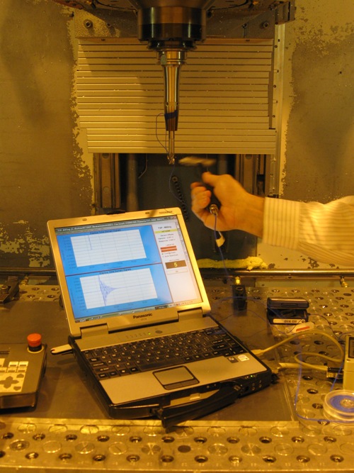
Measuring a machining center’s dynamic characteristics involves tapping it with a light hammer and measuring the response. Every combination of machine, toolholder and tool will produce a different vibration signature. However, the contributions of the tool and toolholder can be modeled mathematically, so they don’t necessarily need to be measured.
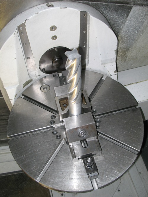
The model for mathematically predicting the dynamic characteristics of tooling was developed at the University of Florida, where this photo and the following photo were taken. To validate the model, a giant end-mill-shaped structure was milled out of aluminum so that the shape could be tap tested (see next photo).
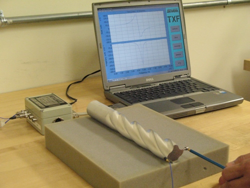
The end-mill-shaped part was placed on foam for the harmonic measurement to simulate it floating free.
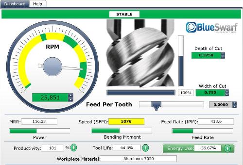
The green regions on the speed dial of this software interface show harmonically stable regions within the rpm range for a particular machining center setup. Within these stable regions are particular, optimal speeds. This photo was taken from an interactive demo on BlueSwarf’s website that makes it possible to see the relative increases in depth of cut and metal removal rate that machining at harmonic sweet spots makes possible.
Share


Many shops using high speed milling spindles are familiar with an odd but useful phenomenon. Namely, high speed machining centers have “sweet spot” spindle speeds at which the heaviest cuts and the most aggressive metal removal rates are possible. These optimal speed values differ for every combination of tool, toolholder and spindle. Nevertheless, by finding just the right speed for a given setup on a given machine, the shop can obtain much more productivity.
In theory, finding these speeds is simple—requiring only a straightforward measurement. In practice, finding and applying these speeds within a production setting is not simple at all. However, two companies providing technology for this sweet-spot milling are now involved in a project that might bring optimal milling speeds within easy reach of all machining center users, even those that aren’t currently familiar with this concept.


Those sweet-spot speeds are a function of machine tool harmonics. Every combination of machine and tooling features some specific set of natural frequencies at which the machining center inherently wants to vibrate. When a cut works against these frequencies, chatter sets in. Yet beyond a speed of about 7,500 rpm, it generally becomes possible to find rpm values at which the cutting edges hit the workpiece in time with a natural frequency. When this happens, the cut becomes smooth. Large axial depths of cut can be taken without inciting chatter.
Thanks to this effect, a machining process with a sweet spot at, say, 16,410 rpm might achieve a metal removal rate at this particular speed that is several times greater than what the machine could achieve at even a much higher speed. The stable cutting would also be smoother than what the process could achieve at a slower speed. If the machine chattered at 10,000 rpm, for example, the impulse might be go slower, but the better response would be to go up instead of down, achieving quiet cutting at 16,410 rpm.
Untapped Potential
Two technology firms that specialize in this phenomenon are Manufacturing Laboratories Inc. (MLI) and BlueSwarf. MLI produces the “MetalMax” system for discovering machining-center sweet spots. BlueSwarf is the master distributor for this system. Because the former company co-founded the latter, MLI owner Dr. Tom Delio is part of the management of both. He says the two companies recently discovered that, in a way, the most effective way to use this machining phenomenon also might be found by going up instead of down.
With the MetalMax system, a shop finds optimal speeds by using a light hammer to tap a tool inserted in a machining center’s spindle. Software measuring the vibration response then determines rpm ranges where the most productive machining will occur. Straightforward as this may sound, though, the ease of use by itself is not enough to make harmonics uniformly practical to apply. Ideal frequencies change with each type of tool or toolholder. The frequencies even change when the tool overhang length changes. Thus, a shop hoping to apply this technology throughout its process has to test every combination of high speed spindle, toolholder and milling tool it is likely to use. Further, the shop has to discipline its programmers to use only those cutting parameters found to be ideal for each combination. While many machining facilities have taken these steps, most are not prepared to implement such a sweeping and determined process change.
BlueSwarf initially responded to this challenge by thinking small, says Dr. Delio. The firm devoted its energy to consulting, equipping one shop at a time to run at optimal speeds. Technicians would visit shops to personally perform frequency-response tests—called “tap tests”—and to assist the shop’s programmers in applying the findings. The firm still provides this service today.
However, a new idea has now taken hold, Dr. Delio says. Rather that settling for the slower pace of in-person consulting, what if there were a way to scale up the sweet-spot phenomenon? That is, what if there were a way to permit a far broader use of dynamically stable parameters than what MLI or BlueSwarf had imagined before?
Consider this:
Every time either of these companies tap-tests a machine, the signature for that particular model is captured. MLI is growing a database of machining-center frequency responses in this way.
Meanwhile, a toolholder and a milling cutter are both geometrically simple enough shapes that their frequency response characteristics do not have to be measured physically. They can be modeled mathematically. The University of Florida’s Machine Tool Research Center, under the direction Dr. Tony Schmitz, has been working for years to refine precisely this theoretical modeling. And if the vibration signatures of the machine, toolholder and tool are all individually known, then they can be mathematically summed together.
Imagine, therefore, if the dynamic characteristics of all the machining centers, toolholders and milling tools were contained in one database. A user of this database could simply select his or her machine from a menu, select the toolholder and tool in the same way, and learn from these selections what cutting parameters will deliver the best cutting for that combination.
Through the use of this utility, just about every shop with a fast machining center would be empowered to run more productively. The shops wouldn’t have to tap test any of their own machines. They wouldn’t even have to keep track of their own sweet-spot parameters.
MLI is now working to develop exactly this utility. The company says it is perhaps 2 years away from launching it and putting it online. The project has received a selection letter indicating likely funding from the U.S. Military’s Defense Advanced Research Projects Agency (DARPA). That funding will be used to measure significantly more machining center models, in order to get the database more complete.
The precedent Dr. Delio sees for this “mapping” of the universe of machine tool harmonics actually lies outside the machine tool industry. He compares it to the mapping of the human genome. Just as that project mapped human genes one by one, this project will map the dynamic characteristics of machine tools and milling cutters. In fact, this very analogy has provided the project with its name. The research aimed at creating this machining database—and the project that won the DARPA selection—officially goes by the name, “The Machine Tool Genome Project.”
Some Numbers
Just as with the original genome project, the mapping of the machining center “genome” will take time. The number of machining center models in current use is (to say the least) large. Further, that number pales beside the number of milling tool models. These numbers are so large that no comprehensive database would ever exist if all of the frequency response data could only be obtained through physical tap testing. However, the freedom to measure only the machines, obtaining the rest of the information mathematically, brings the number down to a size that—though still large—is manageable.
BlueSwarf co-founder Dave Barton finds 3,053 current machining center models sold by 229 builders, according to Techspex.com. Many of those machines sell just a few units per year, he says. Sticking to machines sold in moderate volumes should significantly reduce the number. Similarly, there are 72 makers of milling toolholders, but not all of the product offerings are used widely, nor are they all used in higher-rpm operations. Finally, out of 110 makers of cutting tools for milling, many of the tool models are similar enough that they would not require separate frequency response modeling. Taking all of this together, Mr. Barton estimates there are probably 70,000 distinct items that the database would have to include. That number also includes workpiece materials, so that the utility can recommend not just accurate spindle speeds based on machine and tooling harmonics, but also accurate depths of cut based on spindle power and material properties. Logging 70,000 items is “very manageable and achievable,” he says.
Still, an initial DARPA grant would be spent before all the data are captured. Remaining funding might come from a phase-two grant, and might also come from certain large manufacturing companies that are already involved in the project. Funding might also come from machine tool suppliers interested in obtaining early use of the system, Dr. Delio says.
Involving machine tool builders will also offer a side benefit, he says. These companies have access to their own existing machines. A service technician who visits an older-model machine can quickly tap that machine and add its data to the system. Ultimately, Dr. Delio hopes every machine tool builder will want to do this, because it will be to the builders’ advantage for the Machine Tool Genome Project utility to be able to provide parameters for efficient cutting on that company’s own machines.
Tuning Up
In fact, shops will do even more with the utility than just obtain parameters, predicts the University of Florida’s Dr. Schmitz, who is a consultant to the project. He says shops will also use it to improve parameters—engineering the parameters they want. By trying different choices within the utility, shops will obtain the highest material removal rate they can get on their machines.
Consider again the case where the machine’s sweet spot occurs at 16,410 rpm. The high material removal rate at this speed is a result of the cut being stable enough here to take a heavy depth of cut. But what if that same machine came with a top spindle speed of 20,000 or 25,000 rpm? The shop would prefer the stable cutting to occur much higher up the speed range, providing a metal removal rate that was even higher still. To achieve this, the shop could experiment within the frequency-response utility by selecting different cutting tools to see whether any particular choice would bring the machine’s stable cutting speed somewhere closer to the spindle’s top speed.
The tool would not even have to change. Tool overhang length is also a contributor to the frequency response function, Dr. Schmitz says. Because the length of the tool’s extension from the toolholder affects rigidity, changing the amount of overhang length can move the sweet spot up or down along the rpm scale. In the near future, he says, shops will routinely “tune” their machining processes in just this way—entering different tool overhang lengths in the utility to find the value that is most advantageous to the productivity of the cut. And they will do this without ever having to measure the actual harmonics of the machines that will benefit from this tuning.


Related Content

Automation is for Everyone
Not just for large shops, automation can help even the smallest shops solve labor challenges and become more profitable and efficient.
Read More
How to Successfully Adopt Five-Axis Machining
While there are many changes to adopt when moving to five-axis, they all compliment the overall goal of better parts through less operations.
Read More
The Future of High Feed Milling in Modern Manufacturing
Achieve higher metal removal rates and enhanced predictability with ISCAR’s advanced high-feed milling tools — optimized for today’s competitive global market.
Read More
10 Robotic Solutions You Can Find at IMTS 2026
Discover how today’s robots and cobots are making it easier than ever to automate tasks, free up skilled workers, and run machines unattended – even in small and midsized shops.
Read MoreRead Next

Dial Down or Dial Up?
Vibration analysis may be the machining center’s missing piece. If you haven’t performed this analysis on your high speed machine, you probably don’t know what the machine can do.
Read More
OEM Tour Video: Lean Manufacturing for Measurement and Metrology
How can a facility that requires manual work for some long-standing parts be made more efficient? Join us as we look inside The L. S. Starrett Company’s headquarters in Athol, Massachusetts, and see how this long-established OEM is updating its processes.
Read More