
Calibrating Threaded Plug Gages
Just like gage blocks provide the basis for dimensional measurement, threaded plug gages are the fundamental tools used to verify that an internal thread is correct. Different types of threads serve different purposes, so there are many different threaded plug gages. As with any reference standard, these threaded plug gages need to be inspected to ensure that they are within their original specification.


George Schuetz

The major diameter is checked by placing the test piece between the reference and sensitive jaws in the gage.
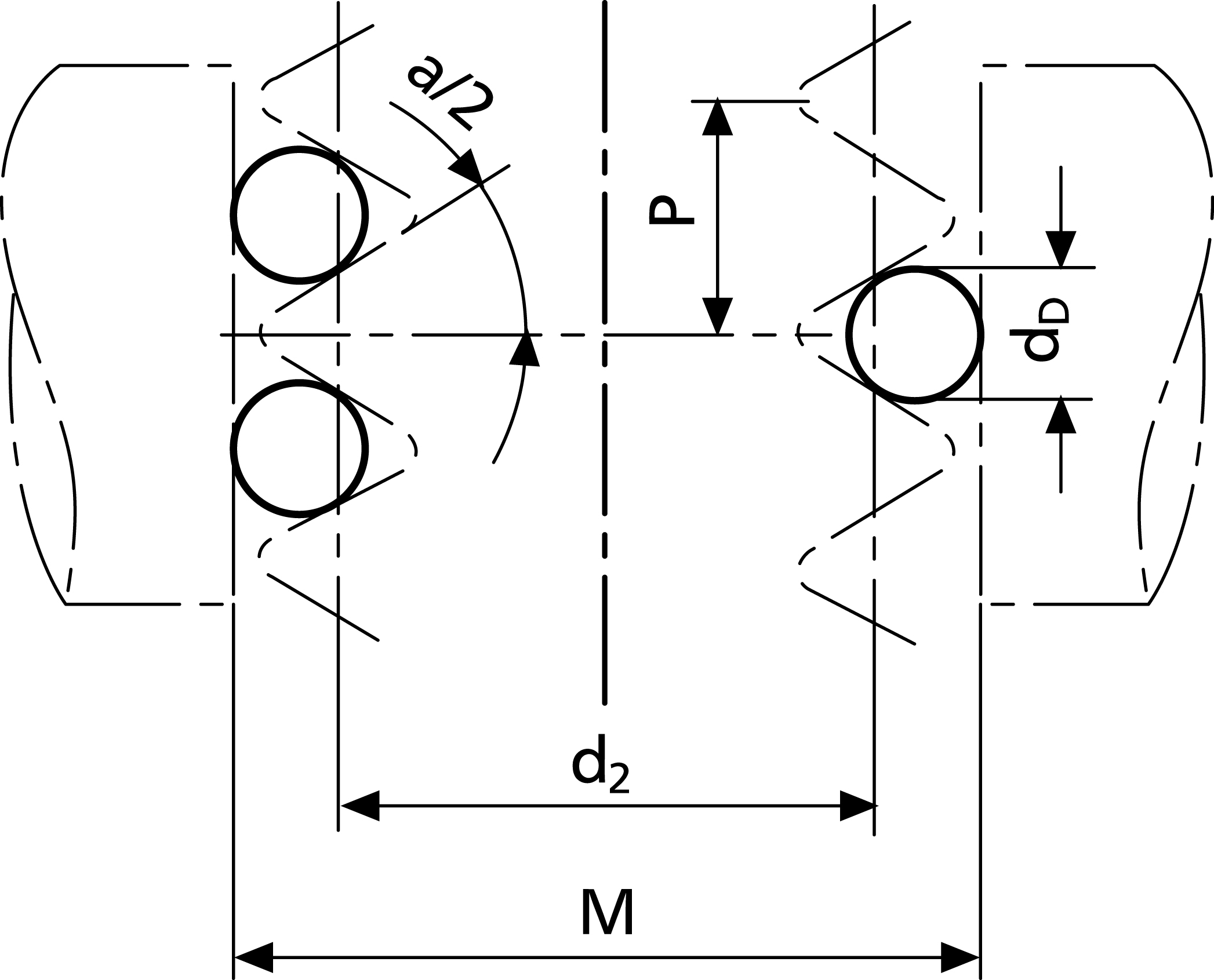
FIG. 1
Share


Phillips Corporation
Featured Content
View More


Phillips Corporation - Education
Featured Content
View More


Just like gage blocks provide the basis for dimensional measurement, threaded plug gages are the fundamental tools used to verify that an internal thread is correct. Different types of threads serve different purposes, so there are many different threaded plug gages. As with any reference standard, these threaded plug gages need to be inspected to ensure that they are within their original specification.
There are many dimensional characteristics on a threaded plug gage that can be measured, but the two most common checks that need to be certified are the plug gage major diameter and the pitch diameter. As with other dimensional standards, there are industry standards that define how thread standards must be calibrated. In this case, ASME B1.2 is the one to reference.
The key to any measurement of gage variation is to use a calibration gage and tools that have proper geometric contacts. Both need to be accurate and sensitive enough to do the thread calibration. For example, when measuring the major diameter of a threaded gage plug, the measurement device’s anvils must be large enough to span the thread’s OD. In addition, the anvils must be sufficiently parallel to reduce the potential of introducing unwanted gage errors. The industry standard specifies parallelism of 4 microinches (0.1 micron) or better. The specification also notes that the resolution of the measuring system should be 10 microinches (2.5 microns) or better. Of course, these two callouts alone do not make for a perfect measurement. The gage needs to be checked by trained operators using proper reference standards in an appropriate environment.
The major diameter is checked by placing the plug gage between the reference and sensitive jaw in the gage. The specification states the number of measurements to be made on the threaded plug along with the proper gaging pressure. The gaging pressure is typically the same as is specified for the second most common check on the threaded plug—the pitch diameter.
The “three-wire method” is the only acceptable procedure used for checking thread pitch diameter, as defined by the ASME specification. Unfortunately, there is no easy and direct technique for taking a pitch diameter measurement, even though it is the most critical measurement on the threaded plug gage.
The three-wire method involves locating segments of wire of a known diameter at three places on the thread and using a measuring machine to determine the diameter over the three points of wire. The key to an accurate reading is selecting the “best size” wire diameter for the measurement. These wire sizes are selected based on the threads per inch and are usually found in a table of thread elements.
The gaging pressure is also specified, and it is based on the gage plug’s threads per inch. For example, if the plug has 20 or fewer threads per inch, 2.5 pounds of gaging force is required. At the other extreme, if there are 140 threads per inch or more, then only 2 ounces of gaging force is used.
To calculate the pitch diameter using the “best size” wire, refer to the table of thread elements to choose both the thread wire size and the “best size constant,” which corrects for the diameters of the wires and the amount they protrude from the thread when measured over the wires. Look at the following example:
|
Plug thread size
|
¼-20 |
|
“Best size” wire
|
0.02887" |
|
“Best size” constant
|
0.04331" |
|
Gaging pressure
|
2.5 lbs |
|
Actual measurement “over wires”
|
0.263801" |
| Threaded plug actual size (actual measurement “over wires” minus the “best size” constant) |
0.2202" |
The specification also requires taking a number of measurements at various locations along the thread to ensure that the pitch diameter size is constant and within tolerance over its full length.
You will also note that in Figure 1, the location of the wires is pretty clear. For most threads, there is not much of an issue making the measurements because the three wires make a pyramid and provide stable fixturing of the threaded plug between the anvils. For plug gages that are small and have very fine threads, there may be a tendency to move the two wires on the one side further apart and skip a few threads to make for a more stable platform. This may be a good idea, but it would not be in compliance with the
specification.


Read Next

WEBINAR: From Machine Data to Guided Action: How Modern Shops Are Closing the Execution Gap
In this webinar, MachineMetrics Product Manager Josh Fish is joined by Pindel Global Precision's Thomas Deslongchamps, for a candid look at what closing the execution gap actually looks like inside a precision machining shop.
Read More