
Understanding Errors In Hand-Held Measuring Instruments
Different instruments (and different operators) are prone to different errors.
Share


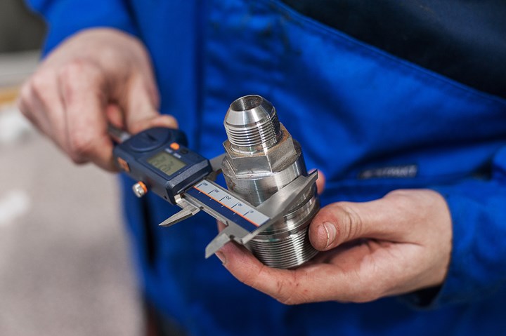
A caliper's fingers have wiggle room. To minimize error, measure with the part as close to the rail as possible.
Photo Credit: Getty Images
Measuring instruments have certain common errors built right into them, and the instruments most commonly used in machine shops are no exception. Recognizing these errors is a basic requirement for proper inspection. It’s not necessary to comprehend the precise physics or geometry underlying the error, but it is important to understand the nature of the error and the extent to which it might affect or limit the instrument’s precision.
Take the micrometer. This is a very accurate and stable instrument, but even this instrument has a certain capacity for error built in. Over-tightening the micrometer’s spindle can cause the anvil portion of the gage to change shape. Lower-quality micrometers are made of materials more prone to this error. While the amount of deflection may be only 0.0001 or 0.0002 inch, that could be 50 percent of some tolerance bands.


Calipers
A caliper is prone to error described by “Abbé’s principle,” which says that a source of error is introduced anytime the reference line of a measuring system doesn’t lie along the same line as the dimension being measured. On a caliper, the scales or gears are not in line with the measuring faces or contacts. As a result, the caliper shifts and wiggles (in microscopic increments) in a way comparable to that of a table or chair when the legs become loose. The error can be minimized by measuring as close to the rail as possible.
Another error limits the instrument’s effectiveness at measuring an internal diameter. The design of the standard caliper places the measuring contacts or jaws offset from one another. That means the jaws will never “find” the maximum diameter of the workpiece.
One other matter to keep in mind with a caliper is the additive nature of the error amounts that are permitted by the instrument’s calibration. To pass calibration, a dial caliper with 0.001-inch resolution must be accurate within ±0.001 inch for length measurements and allow no more than 0.001 inch for parallelism error. But the measurement of a large part may be affected by both errors. In such a case, the possible error is 0.002 inch. According to the 10:1 rule, that means the instrument should inspect a characteristic only if the total tolerance is 0.020 inch or more.
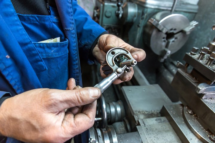
Among hand-held instruments, the micrometer is particularly accurate and stable. About the only built-in source of error comes from the danger of over-tightening the spindle.
Photo Credit: Getty Images
Indicators
Indicators are prone to at least two common error sources resulting from the mechanics of how they work. One is cosine error. This error is particularly likely with a test indicator, which is the type of indicator that uses a tilting lever arm to measure a part moving underneath it. In a correct measurement setup, the lever arm is adjusted so that the movement of the tilt is as close as possible to being perpendicular to the measured surface.
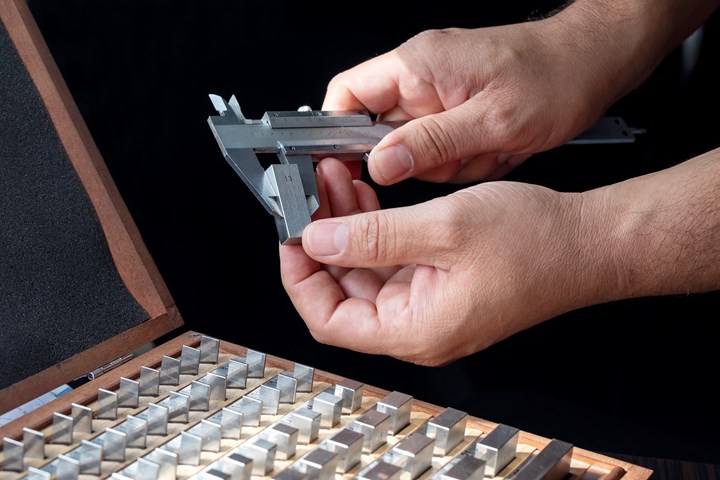
The test indicator can check for the presence of cosine error. The check involves a confirmation of the thickness difference between gage blocks that are 0.100 and 0.103 inch thick. The lever arm should be adjusted so that it will tilt along a line very close to being straight up and down. If this is done successfully, then when we move from one gage block to the other, the dial reading should show a change of 0.003 inch.
The same test can be used to illustrate cosine error by changing the tilt so that this error is created. A subtle adjustment created an error of 0.0003 inch. If this doesn’t seem like much, consider that it represents a 10 percent difference. Imagine trying to match a flatness, parallelism or roundness characteristic to the print tolerance when your indicator is reading 110 percent of the actual value.
The other error common for indicators is hysteresis. This term refers to a lag between action and reaction in a mechanical system. An example of hysteresis is the “play” that may be detectable in a car’s steering wheel. The steering wheel turns a tiny amount before the car’s wheels begin to change direction. Indicators have this play, too. As precisely as the indicator may have been made, it still needs some clearance between gear teeth. If you push the plunger of a dial indicator up from its rest position, there will be a very short duration during which the plunger is moving but the gear that moves the indicating hand on the dial face has not yet begun to move.
How often is a dial indicator moved along a surface to measure a taper or step? There will be hysteresis error in any such measurement because of the small delay before the indicator’s movement causes the indicator hand to move. The error is very small, but the point to remember is that errors compound. An error allowed at calibration, combined with cosine error, combined with hysteresis, combined with a part not being cleaned sufficiently, can create more error than most would suspect.
Measurement Variation
C. E. Johansonn, the first one to mass produce and market gage blocks, once observed that “No two things are exactly alike, and if they were, we would still get different values when we measured them.”
Measurement variation is present every time a part is measured. In some cases, when using a caliper or a 0.001-inch dial indicator, the step of the gage increment is large enough to hide most of the variation. In other situations, the 10:1 rule will require that an instrument of 0.0001- or 0.00005-inch resolution be used to inspect the part feature. When anything is measured to this level of discrimination, the measurement becomes a shade of gray instead of black or white.
Here are some common types of variation:
- Instrument variation. Not all instruments repeat as well as others. A vernier micrometer of 0.0001-inch resolution may be more stable than a digital micrometer of 0.00005-inch (50 millionths) resolution. And differences in measurement variation between a micrometer and a caliper can be large indeed.
- Part variation. The true form of a supposedly flat surface or a supposedly cylindrical bore can depart considerably from the expected ideal. For there to be confidence in any precision measurement, there needs to be a specific, agreed-upon definition as to what each measurement means and entails.
For example, measuring a particular bore may entail measuring the diameters in the X and Y directions at each end of the bore as well as in the middle. The diameter of the bore may be defined as the grand average of all of these values.
- Operator variation. Everyone measures a little differently from everyone else. This seldom means anyone is “wrong.” However, if subtle differences from one operator to the next aren’t addressed, then we could all be wrong as a group. Reference standards—sample parts of known measurement that can be used to make a quick confirmation of a gage—can be used to identify individual measuring tendencies. For example, one operator may consistently measure a tenth on the plus side compared to the rest of the shop. Further variation comes from the simple fact that we all have good days and bad days. Given these circumstances, reference standards can help the overall team. Making a quick measurement of the reference standard just before the critical feature is measured can ensure that a particular combination of operator and gage is measuring accurately at that moment. Think of this as a variation on the maxim, “Measure twice, machine once.”
Repeatability and Reproducibility
The most common terms used to describe measurement variation are repeatability and reproducibility. “Repeatability” describes the range of values obtained when a single operator measures the same part several times. For example, Operator 1 may measure a plug five times with the following results: 1.4948, 1.4948, 1.4949, 1.4951 and 1.4950. We could say the repeatability of the measurement was 0.0003, which is the difference between the highest and lowest values obtained during the test.
“Reproducibility” describes the difference between the average measurements obtained by two or more operators. Operator 2, for example, may measure the same plug and obtain the results 1.4950, 1.4952, 1.4951, 1.4952 and 1.4952. While Operator 1’s average was 1.4949, Operator 2’s average was 1.4951. The reproducibility of the measurement is the difference between the averages, 0.0002. (And Operator 2’s repeatability is also 0.0002.)
What these numbers mean is that, on any given day, the two operators might measure the same feature 4 or 5 tenths differently. Which operator is right? They both are, because that level of variation falls within the range of the combined value of reproducibility and repeatability.
So what is the diameter of the plug? It may be as small as 1.4948 or as large as 1.4952. Using this particular measurement system, it may not be possible to know any more accurately than this.
“Know the uncertainty” is not an oxymoron. Instead, understanding sources of error and understanding the scope of variation are important requirements for getting meaningful results from even the most familiar measuring device.
About the author: Richard Clark is a metrologist working in Portland, Indiana. He can be contacted at rcmetrology@yahoo.com


Related Content

Marathon Precision’s Engineering Playground: One Shop’s Secret to Sustaining High Tech, Low-Volume and High Morale
Half an airplane on the wall, a ten-foot metal dragon, and a full-blown recording studio might not scream “manufacturing efficiency,” yet Marathon Precision proves otherwise. Here’s how forging, complex CNC operations and staff-driven creative projects combine to fuel the shop’s productivity and profitability.
Read More
How to Evaluate Measurement Uncertainty
Manufacturing and measurement are closely coupled. An important consideration for the use of measurement results is the associated measurement uncertainty. This article describes common metrology terms and provides an example uncertainty analysis.
Read More
Machined Part Geometry Measurement
Uncertain about uncertainty? Having trouble remembering the difference between accuracy and precision? Read on to review key metrology terms relevant to the ISO Guide to the Expression of Uncertainty in Measurement (ISO GUM).
Read More
Using Digital Tap Testing to Measure Machining Dynamics
Tool-toolholder-spindle-machine combinations each have a unique vibration response. We can measure the response by tap testing, but we can also model it.
Read MoreRead Next

OEM Tour Video: Lean Manufacturing for Measurement and Metrology
How can a facility that requires manual work for some long-standing parts be made more efficient? Join us as we look inside The L. S. Starrett Company’s headquarters in Athol, Massachusetts, and see how this long-established OEM is updating its processes.
Read More