
Using Digital Tap Testing to Measure Machining Dynamics
Tool-toolholder-spindle-machine combinations each have a unique vibration response. We can measure the response by tap testing, but we can also model it.


An important step in discrete part production by milling is toolpath generation by CAM software. When selecting the CAM parameters, including radial depth of cut, axial depth, feed per tooth and spindle speed, the vibration response of the tool-toolholder-spindle-machine combination, and sometimes the workpiece, must be considered. This is due to the vibrations that occur during machining. These can be characterized as forced vibration and self-excited vibration (chatter).
In forced vibration, the cutting force and corresponding vibration repeat from one tooth to the next. This gives the consistent surface finish that jobs require. When chatter occurs, large cutting forces, poor surface finish and potential damage to the tool and workpiece occur.


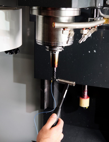
To determine which parameter combinations cause chatter, we require the information contained in the frequency response function, or FRF. This describes the vibration response divided by the force input in the frequency domain. To measure the FRF, we use tap testing. The photograph above shows a modal hammer being used to tap a tool tip and an accelerometer being used to measure the vibration response. The FRF enables us to identify the natural frequency, stiffness and damping for each vibration mode. The value of this information is that we can use it to generate a stability map. This map separates spindle speed-depth of cut combinations that produce chatter from those that do not. When this information is available at the CAM stage, the test-and-check approach of confirming part programs can be reduced or eliminated.
What if FRF measurement capabilities are not available? To address this challenge, we can complete digital tap testing. In this approach, we apply the receptance coupling substructure analysis (RCSA) algorithm to couple an archived measurement of the spindle-machine dynamics to models of the tool and toolholder [1-2]. The predicted tool-toolholder-spindle-machine FRF can then be used to generate a stability map.
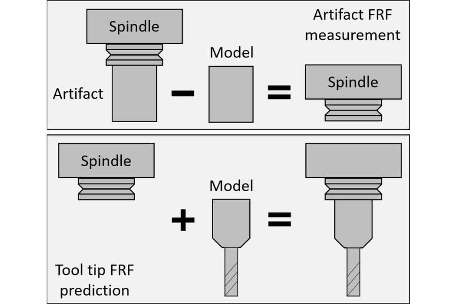
The figure shows the digital tap testing sequence. The top panel shows the FRF measurement of an artifact inserted in the spindle. This measurement is performed once and the result is archived. The portion of the artifact beyond the flange is then removed in simulation to isolate the spindle-machine dynamics. Models of the selected toolholder and tool are next coupled to the spindle-machine dynamics to predict the tool-tip FRF. This is depicted in the bottom panel of the figure. This digital tap test provides the information we require for the stability map and informed selection of optimal milling parameters is made possible.
Related Content
-
5 Things CNC Operators Must Know About Sizing Adjustments
For CNC operators, sizing adjustment is an essential skill. Keep these points in mind when training new CNC users.
-
How To Calibrate Your Calipers
If you’re interested in calibrating your own digital, dial or Vernier calipers, here are some steps to take to make sure it goes off without a hitch.
-
Building an Automation Solution From the Ground Up
IMTS 2022 provides visitors the opportunity to meet with product experts to design automation solutions from scratch.


