A Virtual Jog Mode for CAM
This CAM feature allows tool paths to be defined through a process that resembles jogging the machine manually.
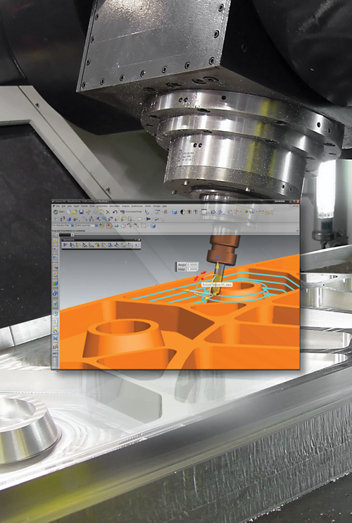
Jogging the axes at the machine tool is one way to execute machine motion in the real world. Siemens PLM’s Generic Motion Controller enables programmers to use a version of jogging in the virtual world to define specific machine moves in CAM.
Dynamic handles enable the programmer to manually define tool position and orientation. Moves created by “teaching” within the virtual environment in this way can be associative, updating as details of the part geometry change.
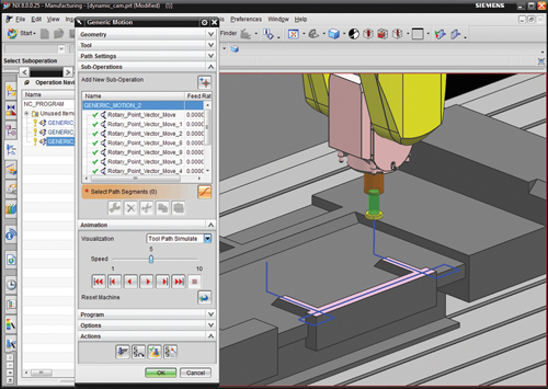
Here is a tool path that would typically require drive geometry modeling. Instead, the programmer can drag machine components in CAM to easily create unusual and specific machine moves such as this.
Share


Phillips Corporation - Education
Featured Content
View MorePhillips Corporation
Featured Content
View More


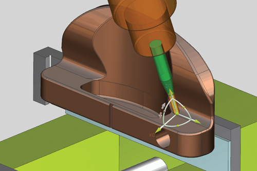
Onscreen graphical interaction with the cutting tool and part continues throughout the NX system. For example, to define a tool axis, the user positions the tool near the area to be cut and dynamically manipulates the handles attached to the tool display. For an interpolated tool axis option, the tool is shown at all four corners of the area to be cut along with dynamic handles. These handles can also be snapped to part geometry to preserve associativity.
Related Content
-
Building a Foundation for AI Success on the Shop Floor
Strong ERP infrastructure and proper planning enable shops to harness the power of AI.
-
Setting Up the Building Blocks for a Digital Factory
Woodward Inc. spent over a year developing an API to connect machines to its digital factory. Caron Engineering’s MiConnect has cut most of this process while also granting the shop greater access to machine information.
-
4 Commonly Misapplied CNC Features
Misapplication of these important CNC features will result in wasted time, wasted or duplicated effort and/or wasted material.


