
4 Ways to Establish Machine Accuracy
Understanding all the things that contribute to a machine’s full potential accuracy will inform what to prioritize when fine-tuning the machine.


Reader Question:
Our shop continues to progress into more complex parts with much more difficult print requirements. As we identify more accuracy equipment, the costs go up significantly for what appear to be the same thing. Can you explain what we should be concentrating on when it comes to machine precision and help us understand where our money is going?
Miller’s Answer:
A spec sheet is nice, and a lot of marketing literature will brag about hand-scraped surfaces or build quality. While these imply accuracy, we don’t really know a machines full potential until we cut parts. With that said, it is important to understand all the things that contribute to a machine’s full potential accuracy, as this educates where the priorities should be. There are four primary ways to establish a machine’s accuracy.


Geometric Accuracy (Static Accuracy)
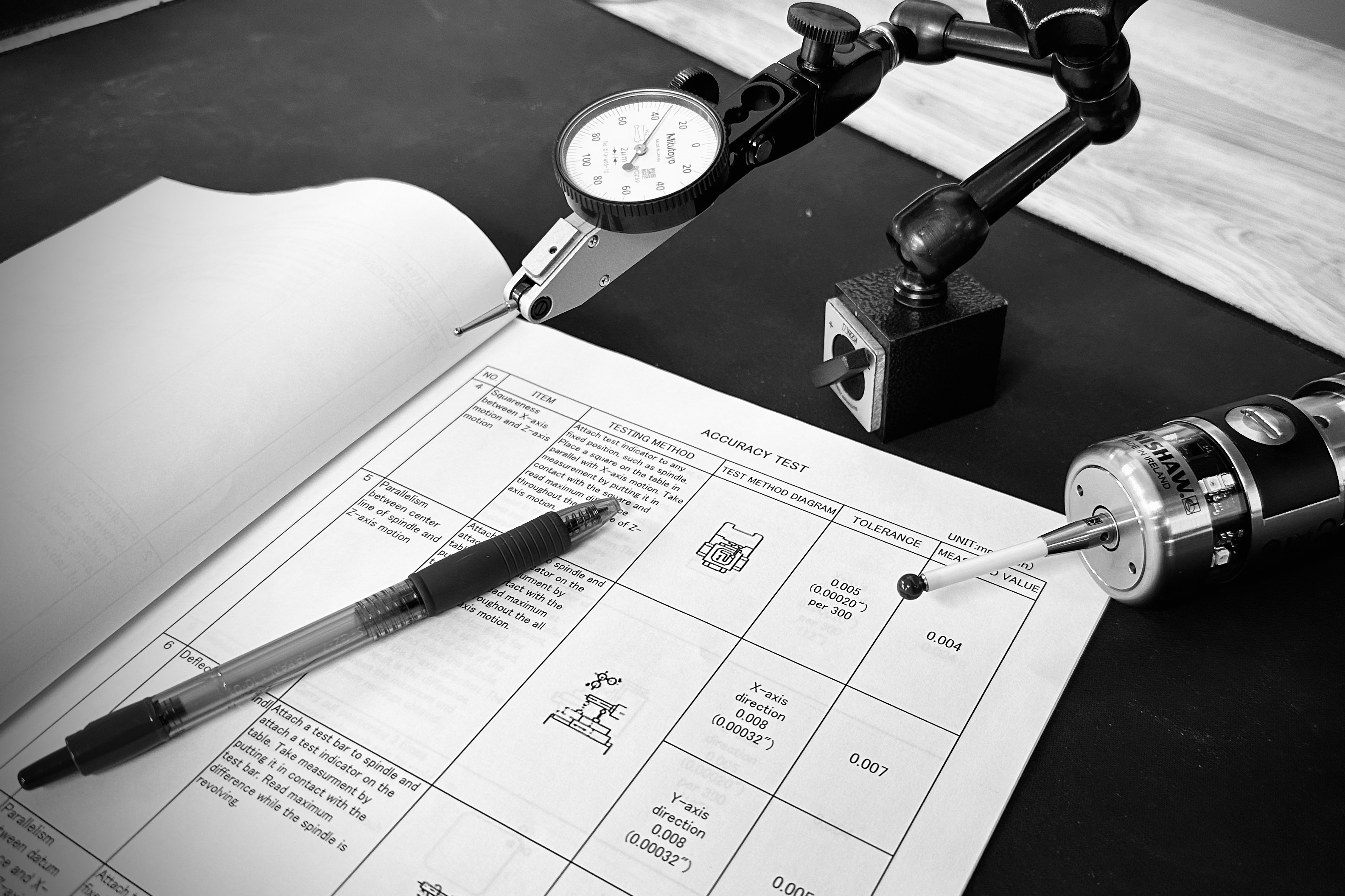
The first way in which a machine can be accurate is by its geometry, or how true the machine structure and its critical components are to itself. This is often referred to as static accuracy, as the machine is measured in its least active state, and it concentrates on two components based on the individual axes, spindle and table. It is measured with a dial indicator and ceramic square.
With regard to the axes, this refers to the straightness of each individual axis, and how square those axes are to each other. For example, if you cut a square profile on the XY plane, would it produce a square with true 90-degree corners and straight sides or would it be a parallelogram with wavy sides?
The second component of geometric accuracy is how perfect or imperfect the critical machine components like the spindle and table are, and how well they are assembled to the axes. This confirms things like spindle runout and spindle point, which confirms the spindle’s center axis is in line with the Z-axes of the machine, along the X- or Y-axis. The machine table is also critical to the static alignment of the machine, and we can confirm general table shape, as well as high or low spots. The purpose of these checks, drawing on our previous square example, would tell us if the side walls of that square would show taper, and possibly if the top of the square would be flat, or take on a concave or convex shape.
Positioning Accuracy
The next way a machine can be accurate is its positioning accuracy, which is what we all know as the “spec sheet” version of accuracy. This is the precision in which the machine travels to a point along an individual axis, and how repeatably it can drive to the same point when commanded. This is usually measured with a laser.
If we continue with the example of our square part, accuracy and repeatability would determine how perfect the overall length, width and height of that square would be, and how consistently we could produce that result part after part.
Often, a machine that can repeat can be made accurate through simple controller tuning to parameters such as pitch error; however, a machine that cannot repeat often requires a mechanical repair of some type.
Volumetric Accuracy
If we combine the geometric accuracy and positioning accuracy into one metric, we now have volumetric accuracy. If you drive the tool tip to a given position within the volume of the machine’s working envelope, is the tool tip where we expect it to be, or is it slightly off? This can be measured with a laser or can be a theoretical calculation based on the above results.
Given the error in the shape of the machine and the trueness of each axis, combined with the ability of each axis to drive perfectly to a commanded position, the result is that the tool tip will be somewhere within a given box of where we intended it to be. On larger machines, you will often see this expressed as “error/meter3,” meaning how true can you drive to any given point within a one-meter box.
Dynamic Accuracy
Dynamic accuracy combines all the above factors and adds the element of a program into the mix. While a machine’s shape may be very true, and each axis very repeatable, dynamic accuracy tells us how accurately a machine can execute code without overshooting or corner rounding, and while staying true to the intended shape. It tests the tuning of the servos, the controller’s ability to absorb and execute code and how true each axis stays while under cutting load.
Dynamic accuracy can only be determined with a test cut. While some industry standard examples exist like circle diamond square (CDS), many shops op for their own, which represents the part features that matter most to them. A die/mold shop may develop a part with sweeping surfaces and check this with a scan versus the 3D model. An aerospace shop might develop a test with full five-axis motion. A medical shop may find some balance of these two for five-axis positioning and organic surfacing.
Cost
To answer the question of cost with more accurate equipment, it can be expressed as the sum of the whole. If you haven’t noticed already, there is a progression with accuracy that starts with machine structure, then evolves into the total machine package. If we take a machine with no servos and ball screws, we can still measure static accuracy. If we add the ball screws and servos, we can check positioning accuracy. If we combine these, we can gage volumetric accuracy. Finally, if we combine this with real machine motion from a program, we have dynamic accuracy.
Every micron of error that is massaged out of each of these stages of the machine build takes a lot of practice and tuning versus assembling a standard package of parts made within acceptable tolerances. So, while a more accurate machine may feel like a lot of cost to absorb upfront, it will pay for itself in process reliability for parts that bring more revenue.
Do you have a machining question? Ask the expert. John Miller leans on more than a decade of industry experience to answer machining questions from MMS readers. Submit your question online at mmsonline.com/MillersEdge.


Related Content

What Should Machinists Know About In-Machine Probing?
In-machine probing doesn’t reach the power of CMMs but can still be useful for pre- and mid-process control, as well as for “rough screening” of parts.
Read More
How To Calibrate Your Calipers
If you’re interested in calibrating your own digital, dial or Vernier calipers, here are some steps to take to make sure it goes off without a hitch.
Read More
Determining Out-of-Roundness at the Point of Manufacture
George Schuetz, Mahr Inc.’s Director of Precision Gages, offers these techniques for measuring roundness on the shop floor.
Read More
Building an Automation Solution From the Ground Up
IMTS 2022 provides visitors the opportunity to meet with product experts to design automation solutions from scratch.
Read MoreRead Next

The Cut Scene: The Finer Details of Large-Format Machining
Small details and features can have an outsized impact on large parts, such as Barbco’s collapsible utility drill head.
Read More

3 Mistakes That Cause CNC Programs to Fail
Despite enhancements to manufacturing technology, there are still issues today that can cause programs to fail. These failures can cause lost time, scrapped parts, damaged machines and even injured operators.
Read More