
How to Successfully Transition from Dial Indicators to Digital
Digital indicators bring a wealth of benefits over dial indicators, but simply swapping one for the other can lead to problems in repeatability and process durability.


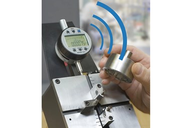
Upgrading an existing dial indicator gage to a digital indicator can provide better discrimination, actual values for the user, dynamic functions, such as TIR, and either wired or wireless data collection.
Photo Credit: Mahr Inc.
Electronic digital indicators can provide higher resolutions, better accuracy, longer range and increased usefulness in statistical process control and data collection systems compared to mechanical dial indicators.
While many digital indicators look alike, there are two specific classes based on the way they measure displacement. The first class is the digital comparator. This uses an electronic, zero-based transducer which typically exhibits short ranges (±2 mm) and offers high performance. The other class, the true digital indicator, is a scale-based system offering a variety of ranges, from a 0-12.5–mm range up through 0 to 100 mm. The shorter-range digital indicators offer adequate performance for most gaging applications. Larger-range digital indicators will have a greater range of error, but still improve upon an equivalent dial indicator.


How Do You Match Digital Indicator Classes to Applications?
Choosing a digital indicator class often comes down to the user’s application. It is very common to replace a dial indicator on a mechanical gage with a digital indicator. Most hand gages, such as snap gages, ID/OD gages and adjustable bore gages, have just a few mm of measuring range; digital comparators may be preferable for these applications. Digital comparators’ ranges match well with gage ranges, and users can position the indicator at its transducer’s electronic zero to achieve optimal performance for both the gage and the digital comparator.
While digital indicators are a large upgrade for these comparative gages, a great deal of the digital indicator’s range goes unused. Often, these digital indicators have a stem or cap on top of the indicator — which can interfere with existing protective covers or, if left exposed, be subject to accidental hits during use. However, for gages such as tri-bore ID gages, thickness gages or bench stands, longer-range digital indicators provide the best combination of ease of use and performance, while also enabling users to start data collection.
How Do You Climb the Digital Learning Curve?
The benefits of digital comparators and digital indicators are well worth the switch, but, as with any improvement, there are some factors users must consider when making the change.
First, consider the performance of the gage onto which the digital indicator is going. Most comparative gages come equipped with indicators that have a resolution matching their performance. For example, a snap gage with flat anvils typically uses a dial indicator with a 2-μm graduation on the dial face. Designs for this type of snap gage usually specify that the device can “repeat within 1 grad” as part of its performance. Trained operators might be capable of “splitting grads” to attempt to measure to 1 μm.
Another type of snap gage, those with blade anvils, typically use dial indicators with 10-μm graduations. This is because a snap gage with blade anvils has less surface to lock in on the part and is more susceptible to operator influence. Knowing this, manufacturers of this type of snap gage would use the dial indicator with the coarser graduation, specifying the gage will repeat to one grad on the 10-μm indicator.
Many of today’s digital indicators have selectable resolutions ranging from 10 μm down to 0.5 μm. Often, users will replace 2-μm grad dial indicators with a digital indicator and try to use the 0.5-μm resolution. In doing so, users “discover” that the gage is not repeating as well as it previously did. In reality, the indicator is probably working just as well as it did, but now the user can see the variability that was lost from the dial indicator. This is not to say there is no hope for better performance out of the gage. Users can lap anvils for better parallelism, bench mount the part to reduce operator influence and clean parts more thoroughly to improve gage performance. Users can also change the indicator resolution to 1 or 2 μm to represent the gage’s true capability.
How Do You Avoid Counting and One-Button Errors?
Replacing long-range dial indicators in bench stands is another great application for a long-range digital indicator. All the benefits are there: Long range, high resolution and the ability to zero out on the anvil and read the dimension size directly, which eliminates the need to count revolutions and interpret the dimension from the dial indicator. In this case, the stem coming out the top of the digital indicator can act as a manual probe traction to get over an obstruction on a part.
Yet even here, there are considerations to remember, again relating to the increased resolution of the indicator enabling users to see previously invisible small errors. One example relates to the simple operation of zeroing out the readout. In the case of a dial indicator, users would bring the contact down to the part and rotate the dial until the hand was on “0” — setting the reference point. The operation is similar with a long-range digital indicator. But in this case, once the contact is on the part, the users needs to press a “zero” or “reference” button to zero out the readout. It is not unusual to see some repeat errors even in this simple zeroing operation, because pushing the “zero” button applies force to the gage. Force can trigger many of precision gaging's greatest enemies. In this case, the force of pushing the zero button travels through the indicator to its mounting, then to the arm holding the indicator and finally through the post holding the arm. Thus, the force will show up as repeatability errors in the gage connections, or will slightly bend or twist the gage’s arm or post. If zeroing the gage never really comes to zero, it is probably a gage issue that users will need to deal with by checking for looseness, employing a more robust stand or reducing the resolution of the indicator.
Even with these minor pitfalls to avoid, digital indicators will continue to replace dial indicators on gages. In fact, many digital indicators are becoming so powerful that they are taking on the performance and features of bench amplifiers. It is not uncommon to find features such as dynamic measurements, multiple factors, unilateral tolerances, different output formats, micron resolution and integrated wireless data transmission in higher-end digital indicators. What’s more, these high-end digital indicators are only about a quarter of the price of a bench amplifier and probe.


Related Content

How to Choose the Correct Measuring Tool for Any Application
There are many options to choose from when deciding on a dimensional measurement tool. Consider these application-based factors when selecting a measurement solution.
Read More
5 Things CNC Operators Must Know About Sizing Adjustments
For CNC operators, sizing adjustment is an essential skill. Keep these points in mind when training new CNC users.
Read More
4 Ways to Establish Machine Accuracy
Understanding all the things that contribute to a machine’s full potential accuracy will inform what to prioritize when fine-tuning the machine.
Read More
6 Machine Shop Essentials to Stay Competitive
If you want to streamline production and be competitive in the industry, you will need far more than a standard three-axis CNC mill or two-axis CNC lathe and a few measuring tools.
Read MoreRead Next

What to Know About Decoding Surface Finish Gages and Parameters
Long-wavelength waviness and short-wavelength roughness require a wide variety of instruments and parameters for proper measurement — and lower numbers aren’t always better.
Read More
Properly Reading Dial Indicators
Dial indicators provide useful readings about tolerance ranges at a glance — but new users need to know how to set up these indicators before using them.
Read More
How to Match Thickness Gage Types to Proper Applications
Different thicknesses require different gage types during inspection — four common ones are handheld indicators, handheld micrometers, opposed air streams and gage blocks.
Read More