
Widening Range Of Grooving Tools
Traditionally, a grooving tool grooves, a facing tool faces and, of course, special tools do special cuts. Improved insert manufacturing technology and toolholder design is changing this tradition, allowing specialized tooling to be used more generically in a wider variety of metalcutting applications.


Side cutting with a grooving insert uses geometry that breaks the chip in three directions. A rigid connection between the insert and tool holder is necessary to reduce deflection.
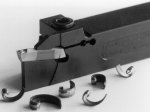
The connection between the tool holder and the insert is critical. In this example, the insert is secured top and bottom by a prism that's molded on the insert. A tab on the tool holder secures the back of the insert to prevent the tendency for the insert to rock during plunge cuts.

Slot milling cutters are increasingly being used in milling operations. These tools can bore, thread and face mill without the need for a tool change.

Straight plunge cutting is a fast method of groove creation. Geometry built into the insert creases the chip so it doesn't mar the sides of the groove.
It seems that in many corners of the metalworking world one sees trends away from the specialized and toward the more generalized. In automotive manufacturing, for example, the big, dedicated, transfer-lines are giving way in many applications to flexible, modular units that can be effectively used for families of similar parts and then re-used for a whole new family of components.
Then there's the idea of machines that turn/mill or, depending on your perspective, mill/turn, which is helping general metalworking job shops and production shops to complete in one setup what took many operations across different tools to machine. And of course there's the machining center, which combines several independent machining operations such as milling, drilling and tapping into a single, one-stop processing center.


Likewise in the cut itself, where the work of metalcutting actually gets done, there have been advances in multiple operation capability from cutting tool builders as well. An example of this is the grooving cutter for turning.
In this article we'll look at how the application scope for these cutters has expanded beyond just grooving and cut-off. We'll also look at the milling cutter equivalent—slotting tools—and discuss how these tools are being applied in new and different ways.
To find out what these tools can and cannot do, we talked to Horn, USA (Franklin, Tennessee) about how to use grooving and slotting tools in applications that fall outside of what has been their traditional niches.
The Force Is With You
The advent of the indexable insert grooving-tool has delivered huge benefits to shops that use them. Advances in carbide pressing technology allow chip breakers and various geometric configurations to be imparted onto even very small width cutters.
The payoff for shops has been better quality both in size and surface finish, not to mention significant increases in cutting speeds resulting in faster cycle times.
During virtually any plunge feed grooving operation, tremendous cutting forces in the form of heat and stress are generated at the tip of the insert. Insert design goals are directed to overcoming these factors. Increased tool life, accurate dimensional repeatability and better surface quality are the results.
The relative contact area between the grooving tool and the workpiece is very narrow. Grooves down to 0.010 inch can be cut with indexable insert tools. Grooves can also be large. In some applications, groove widths of 1.75 inches are plunge cut using an insert with the same width.
Regardless of the groove width, all plunge-grooving operations basically operate in the same way. A Z-axis feed creates axial forces that are directed into the insert edge. The edge is supported (Horn's holder supports 80 percent of the insert's length) by the tool holder body which, in turn, is held in the turning center tool turret. Ultimately, the forces, which on plunge cuts are pretty much straight-line, get channeled into the machine tool base.
There are many standard and special insert sizes, shapes, coatings and substrate combinations available for grooving. Cutting toolmakers have covered plunge grooving well.
However, many shops are extending the use of grooving cutters by performing some turning operations, which is side cutting, with the grooving insert. Moving from a single axis plunge feed to an X-Z axis combination is where shops really see some production gains by extending the versatility of grooving inserts. But there are some process considerations to examine before ripping a contour or turning a face with a grooving tool.
The Force Is Against You
Unlike plunge grooving, which works to the mechanical strength of the insert and holder, turning along the workpiece axis has the opposite affect. Turning exerts radial or side forces on the insert and holder that are trying to bend or deflect the tool. The relatively thin cross section of the grooving tool provides little mass to offset this tendency toward deflection.
Horn and other grooving toolmakers have designed inserts and holders that allow for the deflection from turning without a loss of precision or performance. This is done in several ways.
On combination grooving and turning inserts, geometry is designed and then pressed into the blank creating free cutting in both axial and radial directions. Relief angles on the side of the insert allow chip clearance during side cutting operations. Free cutting geometry reduces cutting forces. Reduced cutting forces reduce deflection.
In most applications where these inserts are applied, the job requires cutting between shoulders. Usually when the distance between shoulders is too large for a single grooving insert to be plunged, turning passes between the shoulders are necessary. Side turning also produces better surface finishes on the sides and bottom of the cut than plunge cutting.
In these cases, Horn recommends a minimum grooving insert width between 0.098 and 0.400 inches. Wider is better for side cutting with a grooving insert. And even with a stiff tool setup, there are some programming considerations for side cutting as well (see box).
It's In The Grip
By its nature, the grooving insert is a tricky shape to grab. This is especially true in smaller widths. It's long and narrow because the cutter is used to plunge deep between relatively narrow shoulders. This shape, unlike a triangle, square or round insert, doesn't provide a large surface area on which to clamp.
Even in plunge cuts, forces are trying to twist the insert out of its seat in the tool holder. Side cutting puts even more demand on the tool holder's ability to hang on to the insert.
To help overcome the side cutting forces, Horn presses a prism shape in the top and bottom longitudinal axes of the insert. This prism fits a corresponding slot in the toolholder clamp. An insert, without some sort interlock shape between it and the holder, will tend to shift or possibly loosen under cutting conditions.
Under clamp pressure, the prism and its receiver on the tool holder secure the insert top and bottom over the full length. This clamping system helps the insert resist deflection from side cutting forces while at the same time maintaining a rigid connection between the insert, holder and machine turret. A rigid connection between the tool holder and insert is a critical consideration for shops that want to side cut with grooving inserts.
Interpolate It
Milling operations too can take advantage of multiple operations using one cutter. An example is the slot-milling cutter. Usually its specialty includes cutting keyways and T-slots. Generally cutting a slot or key involves feeding the X or Y axis while the Z axis is fixed at the programmed depth.
With the advent of circular and helical interpolation on machining centers, the versatility of these typically dedicated cutters has been expanded. Horn and other cutter makers produce indexable insert cutters that can face mill, clean up a bore, scribe a thread, groove, or step inside the bore, all with a single tool. But without interpolation, these operations would require dedicated cutters to perform them.
More Tools-Fewer Pockets
An impetus for shops to get more operations from a given cutting tool is the relatively small tool capacity of most turning center turrets. The ability to load a sufficient number of tools for more than a couple of jobs is often restricted by turret capacity. This extends setup time from job to job.
If a shop can use a grooving tool for two or more operations that would traditionally take individual cutters, it saves those valuable tool pockets for other tools or redundant tools. This extends to the tool room as well, with less insert and cutting tool inventory to stock and maintain.
Slow But Steady
Using grooving tools for side turning is not suggested as a replacement for general purpose turning tools. Likewise, slot-milling cutters cannot perform face milling and boring as well as tools specifically designed for these functions.
However, in an application where turning between shoulders and facing operations or, ID boring with internal grooves are called for, using one tool for several is a good option. In a milling application, the ability to face a surface then interpolate a bore and cut a spiral groove or O-ring slot with one cutter saves cycle time.
The idea behind using one tool for more than one operation is to help shops save cycle time and reduce complexity in some of their processes. Advances in insert pressing and grinding technology along with better substrates and coatings allow inserts to be used in innovative ways. And, when combined with the versatility of the modern CNC machine tool, the cutting tool and machine applied together can help get the job done better, cheaper and faster.


Related Content

New Modular Tool Options for Small Spindle Milling
Tooling options have been limited for small spindle milling applications. Now modular, indexable systems are available that provide broad flexibility to get the right cutter for the job with less inventory and at lower cost.
Read More
Twin Spindle Design Doubles Production of Small Parts
After experiencing process stalls in the finishing stage of production, Bryan Machine Service designed an air-powered twin spindle and indexable rotating base to effectively double its production of small parts.
Read More
A New Milling 101: Milling Forces and Formulas
The forces involved in the milling process can be quantified, thus allowing mathematical tools to predict and control these forces. Formulas for calculating these forces accurately make it possible to optimize the quality of milling operations.
Read More
All-Around Mill Improves Productivity and Cost for Valve Job
Adopting a mill with a double-negative rake and pockets compatible with multiple insert geometries enabled Progressive Metal Service to increase feed and lower scrap rates for a valve.
Read MoreRead Next


3 Mistakes That Cause CNC Programs to Fail
Despite enhancements to manufacturing technology, there are still issues today that can cause programs to fail. These failures can cause lost time, scrapped parts, damaged machines and even injured operators.
Read More
The Cut Scene: The Finer Details of Large-Format Machining
Small details and features can have an outsized impact on large parts, such as Barbco’s collapsible utility drill head.
Read More