
CAM System Proves Integral to Prototype Prove-out
Delcam for SolidWorks CAM software helped this engineering firm relied on to generate the complex tool paths for a prototype job that many machine shops dismissed as too difficult.
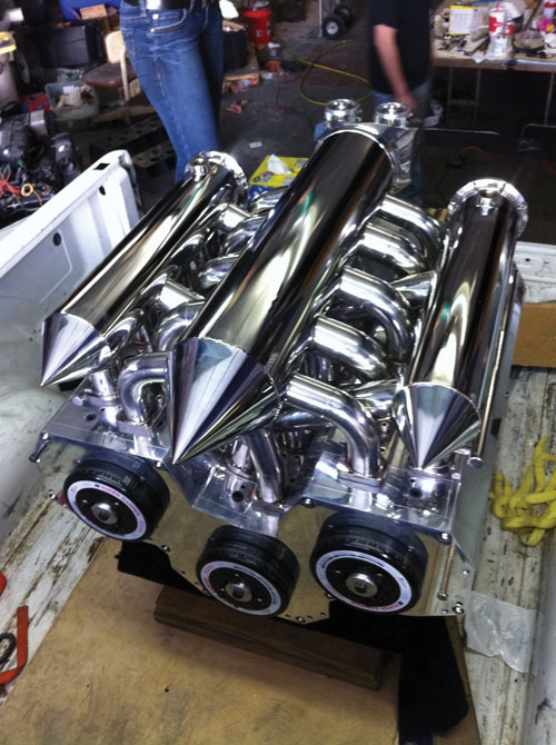
The finished, polished engine loaded in a truck for transport to the Miami Boat Show in February. While the company machined the bulk of the engine on its own, it had a local fabrication shop build the exhaust and intake manifold.
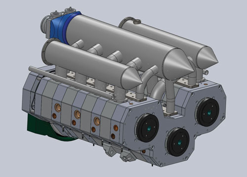
The original SolidWorks design for Stamps Engineerings’ Wankel Engine.
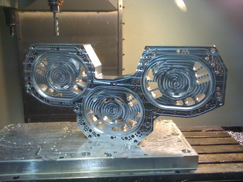
A divider plate for Stamps Engineering's Wankel powerboat engine. This is just one of hundreds of parts requiring complex machining operations.
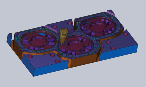
In this screenshot, Delcam for SolidWorks simulates machining operations on an engine divider plate. Simulation enabled Mr. Stamps to ensure operations were proceeding smoothly and that the part would be cut according to specified tolerances.
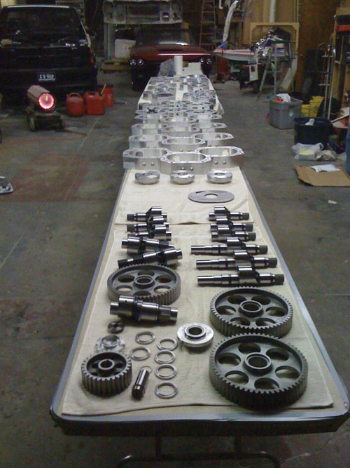
Here, all the components of the new engine design are laid out prior to finishing and assembly.
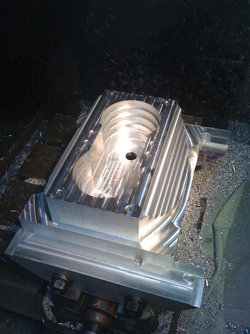
The engine’s inlet adapter, shown here, was cut on a VMC using Delcam for SolidWorks' feature-based machining capabilities.
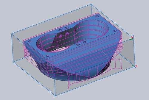
This screenshot from Delcam for SolidWorks shows the boundaries of the features used to machine an inlet adapter for Stamps' Wankel engine. According to the company, the software's feature-based machining capabilities, which automatically recognize features and apply appropriate machining strategies, were critical to producing the engine prototype within the specified timeframe.
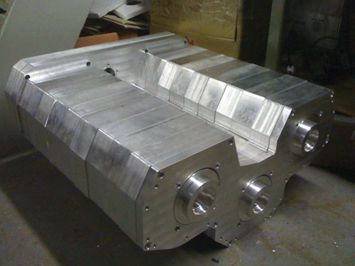
Sections of the motor were lined up as Stamps Engineering completed the bulk of the machining. The external ports still needed to be machined in the sections shown here.


Related Content

IMTS Takeaways From the Modern Machine Shop Editorial Team
The first in-person IMTS in four years left the MMS editorial staff with a lot to digest. Here are a few of our takeaways from the show floor.
Read More
Finally, A Comprehensive Software Solution Designed for Small Job Shops
Zel X from Siemens is an integrated software application that consolidates collaboration, design, manufacturing, and operations into a comprehensive, easy-to-use solution. From RFQ to delivery, it’s a more efficient way to handle quotes, manage jobs, make parts, and collaborate with teams of all sizes.
Read More
Integrated CAD/CAM Promotes Process Efficiency, Traceability
High-requirement markets are not only searching for good parts — they're searching for proof of good parts. CAD/CAM software can help.
Read More
Large-Format Machining With Small Cutting Tools and Dynamic Motion
Napoleon Machine, a defense contractor that provides parts for the M1 Abrams tank, recently took advantage of a CAM feature that allowed the company to streamline its cutting strategies and program offline. Here’s how the shop cut cycle times nearly in half with its large-format five-axis machining operations.
Read MoreRead Next


The Cut Scene: The Finer Details of Large-Format Machining
Small details and features can have an outsized impact on large parts, such as Barbco’s collapsible utility drill head.
Read More
3 Mistakes That Cause CNC Programs to Fail
Despite enhancements to manufacturing technology, there are still issues today that can cause programs to fail. These failures can cause lost time, scrapped parts, damaged machines and even injured operators.
Read More