
Custom Tools For Critical Grooves
This tier-one auto supplier pooled metalworking talents to develop custom groove milling tools to deliver the accuracy and finish necessary for precision brake caliper grooves.
.jpg;width=70;height=70;mode=crop;format=webp)


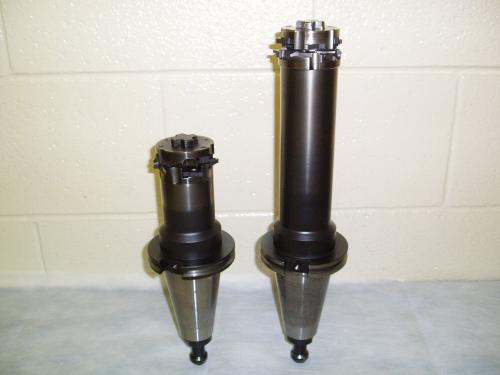
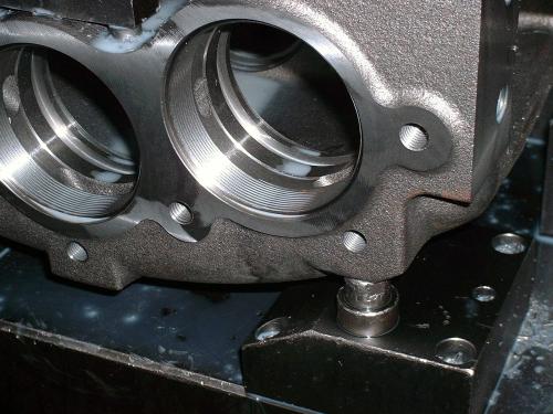
The caliper’s U-shaped geometry adds to the difficulty in machining the two grooves in the back-side bores. A 4 to 1 L/D groove-milling tool passes through the front-side bore to mill both back-bore grooves.
These circular-interpolating groove milling tools use multiple staggered inserts to create each groove’s full groove width. Staggering the inserts creates a smaller chip that is less likely to become stuck in the groove after machining.
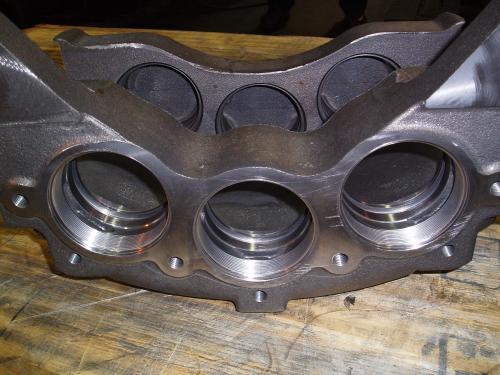
This tier-one automotive supplier uses a custom groove milling tool that simultaneously machines two piston bore grooves in its brake calipers.
There are still some of them out there, though a case may be made that their numbers are dwindling. “Them” refers to the machinists who eat, drink and sleep metalworking—people who are constantly thinking of ways to wring every last drop of production from their equipment. While chatting with Afzal Cheema during a visit to ArvinMeritor’s York, South Carolina, facility, it was clear that he is one of those people.
Mr. Cheema, a 30-year shop veteran, is the tooling coordinator at the 275,000-square-foot tier-one operation that manufactures brake and wheel components for commercial vehicles. Mr. Cheema’s problem-solving drive led him to work with Horn USA (Franklin, Tennessee) and Remco Supply (Arden, North Carolina) to develop a custom groove milling tool for brake caliper grooves. The goal was to improve a machining technique that wasn’t consistently delivering the accuracy or finish required for those grooves.


The caliper’s U-shaped geometry and tight tolerances created challenges in producing the grooves. The original groove machining process used multiple tools and had a 25-minute cycle time and a scrap rate of 20 percent. Mr. Cheema knew that the problem didn’t lie in the capabilities of the various horizontal machining centers that ran the jobs, but rather in the tooling. He pooled the experience of people cut from the same cloth as he—Remco’s Michael Arrington and Horn USA’s Brian Hogg—and together they developed a groove milling tool that could accurately produce two grooves in one operation, greatly reducing cycle time, the number of tools required and scrap rate.
Fit And Finish Issues
The ductile iron calipers that the plant manufactures may have two or three piston bores in both caliper sides, depending on the model. The bores in each caliper side have two O-ring grooves (a three-bore caliper will have a total of 12 grooves). The groove width, taper, concentricity and roundness are controlled to ensure proper piston movement and sealing in the commercial vehicle applications.
Each pair of grooves was originally produced using automatic recess head tools. A long tool and short tool would rough each individual groove, and then two other similar tools would perform the finishing cuts. Because this machining method was not repeatable, an operator would stop the program after the first set of grooves was machined to take measurements. If the grooves were undersized, then the operator would adjust the tool offset and re-cut the grooves. If a groove was oversized, then the caliper was scrapped. Scrapping a cast caliper at this point in the manufacturing process is especially costly, because groove milling is the last machining operation.
Now the plant uses multiple-insert groove milling tools from Horn USA that can simultaneously machine the two angled grooves, as well as a radius and multiple chamfers. This new tool design reduced cycle time from 25 minutes to 8 minutes and scrap rate to virtually zero. Combining grooving operations on a single tool also freed space in the machines’ tool carousels.
Rotating, Interpolating
In circular-interpolation groove milling, a machine tool’s spindle rotates the cutter as the machine interpolates the cutter inside the bore. The caliper’s shape and bore locations dictate the need for two tools. A short tool machines the caliper side closest to the spindle, while a longer tool is required to reach 10 inches through one side of the caliper to the bore in the other side (see photo on page 113). The long tool is able to maintain concentricity at an L/D ratio of approximately 4 to 1. The tool’s shank diameter is limited because it can’t contact the bore through which it passes to reach the other caliper side.
The full groove width is not created with inserts equal to that width. Rather, staggered inserts create the full groove width (there are six inserts for each groove). Staggering the inserts in such a manner eliminates the need for a chip divider to be ground into the insert cutting edge, because staggered inserts serve to cut the chip in half. A small chip is less likely to roll around with the interpolating cutter and remain stuck in the groove after the machining operation and air blow-out. That was an issue with the previous groove-machining method.
The profile of the inserts on the long tool is inverted to create the grooves on the back bores. The triangular carbide inserts, which are indexable to provide three cutting edges, have a positive rake angle that serves to reduce tool pressure. Given the grooves’ tight tolerances, care must be taken when indexing the inserts to ensure that the insert pocket is cleaned to standard industry practice to ensure proper seating.
Mr. Arrington likens groove milling to machining pocket sidewalls. In both cases, any vibration that begins when the tool first contacts the workpiece would continue throughout the entire cut, resulting in a poor surface finish. This situation would likely occur (as would possible tool breakage) if the groove milling cutter were fed into the workpiece at full groove depth and then interpolated around the bore. That’s why the groove milling tool is gradually radiused into the cut as it is interpolated. All features are completed in two interpolations of the rotating tool.
Inefficiency Not An Option
The efforts at ArvinMeritor’s York facility to continually increase manufacturing efficiency are driven by the company’s focus on continuous improvement and eliminating waste. That’s why the company looks to the folks on the front line of its processes, the shopfloor workers, for suggestions to cut manufacturing costs, increase productivity and improve workplace safety. Managers solicit ideas from employees for ways to cut costs through its CI (continuous improvement) program. The program, which was implemented 3 years ago, requires that every employee average two CI suggestions per month during the course of a year. This simple “solution box” system offers a way for workers not only to help the company, but also help themselves to a potentially larger paycheck and more efficient workplace.


Read Next

Widening Range Of Grooving Tools
Traditionally, a grooving tool grooves, a facing tool faces and, of course, special tools do special cuts. Improved insert manufacturing technology and toolholder design is changing this tradition, allowing specialized tooling to be used more generically in a wider variety of metalcutting applications.
Read More

The Cut Scene: The Finer Details of Large-Format Machining
Small details and features can have an outsized impact on large parts, such as Barbco’s collapsible utility drill head.
Read More