
High Performance Twist Drills In Perspective
The trend today is clearly toward high performance twist drills made of tungsten carbide or other premium materials, combined with innovative geometries, tighter tolerances, and advanced coatings. The pressure to reduce costs through productivity gains is driving this change.


Diameter Back Taper/Inch Web At Point Web Increase/Inch Clear Diameter Land Width Margin Width Point Angle Lip Relief Chisel Angle Helix Angle Overall Length Flute Length .2500 .002 .071 0 .242 .189 .014 140° 7° 143° 30° 3.150 1.580

Diameter Back Taper/Inch Web At Point Web Increase/Inch Clear Diameter Land Width Margin Width Point Angle Lip Relief Chisel Angle Helix Angle Overall Length Flute Length .2500 .004 .064 0 .232 .137 .012 140° 12° 139° 30° 3.238 1.690
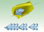
Figure 5—The point geometry of the high performance drill (right) promotes highly effective chip control. Curved edges aviod corners that create breakage-prone stress points.Drill geometries producing chips that are not long and stringy are suitable for high performance drills.
Figure 1 - Standard twist drill terminology is still useful for identifying the design features of a high performance drill.
Figure 4—The point geometry of the high performance drill (right) promotes highly effective chip control. Curved edges aviod corners that create breakage-prone stress points.

Diameter Back Taper/Inch Web At Point Web Increase/Inch Clear Diameter Land Width Margin Width Point Angle Lip Relief Chisel Angle Helix Angle Overall Length Flute Length .2500 .0014 .071 0 .237 .158 .017 145° 5° 135° 29° 2.900 .985

Diameter Back Taper/Inch Web At Point Web Increase/Inch Clear Diameter Land Width Margin Width Point Angle Lip Relief Chisel Angle Helix Angle Overall Length Flute Length .2500 .0005 .076 .002 .225 .160 .020 140° 13° 120° 30° 3.270 1.750
Figure 6—This simple hole drilling test was used to establish performance benchmarks for various styles of HSS and high performance twist drills.
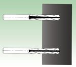
Figure 2 - The drill on the bottom has constant web thickness. The drill on the top has a web that grows thicker, hampering chip flow.
High performance twist drills are continuing to gain greater acceptance for critical hole making operations in the metalworking industry. It's easy to see why. Every shop and plant needs to maximize productivity and improve product quality. Today's advanced machine tools have the capability to exploit high performance cutting tools. What's more, workpiece materials are harder and more difficult to machine, while workpiece geometry is more complex.
Companies are placing more emphasis on sound machining economics. It is widely accepted knowledge that tooling costs represent a relatively small percentage of total process costs. Spending more on high priced cutting tools is advantageous in light of the dramatic contribution these cutting tools make toward achieving low-cost machining performance. In short, the additional investment in high performance cutting tools is easily justified. Hole making operations are particularly important. After all, drills produce more than 70 percent of the chips made within the metalworking industry.


In hole making operations, cost reduction through productivity gains is the chief benefit of these important trends. As a result, drill design has evolved toward new base tool materials, new geometries, tighter tolerances and new generation coatings. These emerging designs may be characterized as "high performance drills."
The designs of high performance drills have evolved over the years. Studying today's drill designs and comparing them to earlier generations of drills is revealing. It is obvious that many design features of a twist drill have not changed substantially and are still found on almost all designs. A twist drill can still be defined validly as a "rotary end cutting tool with one or more cutting lips and one or more straight or helical flutes for the passage of chips and the admission of coolant."
These geometrical components enable the product to create a cavity from a solid. For reference, these standard components are identified by the terms given in Figure 1. Nevertheless, the design features that are critical to performance consist of base material, geometry and application parameters.
Premium Tool Material
The high performance drills that are marketed today are typically configured from the following base tool materials:
- cobalt,
- cobalt with coolant holes,
- solid carbide,
- solid carbide with coolant holes, and
- carbide tipped with coolant holes.
All of these base tool materials are enhanced with a thin film coating.
The purpose of the premium material grades is to improve the drill's ability to withstand the higher heat generated at higher surface footage rates while still allowing for shock resistance required during the drilling process. A dramatic reduction in drilling time accompanies the increased surface speeds possible with premium tool materials and advanced coatings. With these productivity gains, the trend toward premium materials should be no surprise.
In particular, solid carbide has gained popularity as a base material for high performance twist drills. Solid carbide drills optimize drilling performance in ferrous materials for a number of reasons:
- The improved metallurgical properties of the carbide material provide the foundation for superior performance.
- Tougher carbide allows special drill geometries to be created.
- Enhanced thin film technology provides coatings that reduce friction better and last longer.
- Solid carbide fully exploits the higher rigidity and accuracy of today's CNC machine tools.
The user, in turn, is significantly rewarded by using solid carbide drills. Longer tool life results in lower cost per hole. Solid carbide drills allow higher speeds and feeds for greater productivity. Finished holes exhibit less runout and better accuracy. Greater efficiency is realized through reduced machining time, less material work hardening, improved wall finish and reduced post operational costs.
Geometry
Over the years, drill manufacturers have established a critical features list which identifies and prioritizes the value of the components and their impact on performance. It is apparent that a successful drill design is one that properly forms, accommodates and escalates the chips, carrying away heat with the chips.
The primary cause of premature drill failure is chip congestion leading to torsional breakage, thermal wear, or deterioration of hole quality. The secondary cause of premature drill failure is due to heat created by friction.
High performance twist drills achieve their remarkable capabilities through innovations in geometry features. Changes in the design of the drill's web and point geometry are a few good examples.
Web Thickness
The web is the tool's backbone. The web construction, in conjunction with the land values, contributes to the strength of the tool. Various drill designs incorporate different types of web configurations. Most twist drills have a web construction falling into two basic categories. A drill has either a constant rate of increase in web thickness, or a constant web thickness. Figure 2 compares these two web configurations, showing web thickness as if visible through a cross section of each drill as it enters the workpiece.
Figure 3—Drill point geometries display many sililarities but subtle difference as well (Dimensions in inches)
During the drilling process, the tool rotates and moves axially into the workpiece. As the chips are formed and accommodated, the drill's helix assists chip movement away from the cutting edge and out of the hole.
When a drill has a web which is increasing in thickness toward the back of the flute, the chip area decreases as the tool penetrates further into the workpiece. This reduction in flute area can hamper chip flow and lead to tool failure. To avoid this situation, all high performance drills have constant web construction. The rationale is to maintain good chip flow by making the flute area consistent so that the chip does not have to "climb a hill" when exiting the workpiece.
Point Geometry
A look at the point geometries found on drills (see Figure 3) not only shows a wide variety but also some important similarities. For example, many of the designs are patterned around the split point style.
High performance drills take these geometries in new directions (see Figure 4). For example, common knowledge holds that the chisel length accounts for most of the thrust required to penetrate the workpiece. By reducing the length of the chisel, via web thinning, thrust is reduced and penetration is improved. Web thinning also creates additional cutting lips, which assist in chip formation and chip control. Four cutting lips produce four manageable chips for improved chip flow.
The main difference between drills with split points and drills with high performance point geometry is that the secondary cutting edges generally begin to curve outwardly away from the direction of the drill's rotation rather than appearing straight. The purpose is to further assist in chip control, but more important, to eliminate stress points which occur when sharp corners exist.
Flute Forms
The flute form of a drill is extremely critical to its performance. The shape of the flute determines the ability of the drill to form, accommodate, and escalate the chips,thus carrying away heat. A drill is far from being a piece of bar stock with two grooves in it. In the precise geometry of a high performance drill, the flutes are mathematically defined to optimize its performance.
The flutes of conventional drills are typically formed with a shaped grinding wheel which addresses the axis of the drill blank in such a manner as to provide a straight cutting lip, an appropriate land width and a predefined gullet area. This approach not only maintains the drill's strength but also allows for proper chip evacuation.
Over the years, drill manufacturers have experimented with the shape of the flute by altering the shape of the grinding wheel. By changing the shape, chip flow is altered, thus affecting the ability of the drill to accommodate and escalate the chip.
Chip Formation
Chip formation is affected by numerous factors. These include
- workpiece material,
- feed rate/spindle speed,
- point geometry and style,
- helix angle, and
- flute form.
Obviously, different types of chip formation exist in the drilling process. The key is to create manageable chips by manipulating drill design features in such a way that the drill can run at higher conditions, so that regardless of the workpiece material, chips are formed properly. Figure 5 shows how a chip breaks into manageable pieces.
High performance drills are often produced with flute forms identical to those found to be effective on conventional drills. On the other hand, some high performance drills take advantage of alternative flute forms. For example, the grinding wheel shape for a concave-lip high performance drill, which produces short but tightly curled chips, will produce a flute form that allows chips of this shape to flow up and out easily.
Back Taper And Margin Widths
Two other areas of drill design which impact performance are back taper and margin widths. The purpose of back taper is to reduce the heat due to friction while the tool is engaged in the workpiece. Conventional drill designs have back taper values that correspond to standards established within the industry. Most high performance drills, on the other hand, have back taper values that are virtually double those pre-established guidelines. These higher values create more relief while the drill is in the workpiece, minimizing heat.
In conjunction, the margin widths of high performance drills are typically narrower than those of conventional drills. The margin guides the drill through the inner hole wall. For high performance drills to produce a cavity that is very close to drill size and do so at high speed, a thinner margin width is required to reduce rubbing on the inner wall.
Thin Film Technology
A hallmark of high performance drills is the use of thin film technology to enhance performance. These coatings augment the hot hardness properties of the premium base tool material in order to allow it to withstand even higher temperatures within the cut. In conventional drill designs, the primary tool failure modes are associated with heat generation. Because coatings act as a thermal insulator, the amount of heat absorbed by the drill is significantly reduced, allowing for increased production rates.
Various coatings have been evaluated over the years and their worth in productivity increases has been demonstrated time and time again. Even standard high speed steel (HSS) drills benefit dramatically from coating technology, and there is undoubtedly a segment of the market for which these HSS drills will have a lasting place.
Test Results
The most important benefit of high performance drills is the machining parameters they achieve actually producing holes. Tests comparing various styles of conventional HSS drills with various styles of high performance drills are revealing. One such test was conducted in 4140 steel plate ranging in hardness from 30 to 32 Rc. The results of this test are representative of other similar evaluations.
This test involved drilling holes, as shown in Figure 6, and making calculations based upon drilling cycles in order to demonstrate performance ratios. The results summarized in Figure 7 show that the best high performance drill was 20 times more productive than the uncoated HSS conventional drill it was tested against. (A surprising number of such conventional drills are actually being used in industry, so this extreme comparison has more than academic interest.)
However, even coated drills of conventional design performed satisfactorily enough to generate an impressive time savings. This means that users must look at machine cost/time, total tool cost, and ease of handling to see the full value of high performance drills. No doubt, savvy shop managers will recognize the strategic implications of the decision in favor of high performance drills, but further customer education has to occur for the appropriate decision to be made in every case. No cutting tool can be a cure-all.
Continuous Improvement
The concepts applied to twist drills, which are characterized as "high performance," represent an evolution of conventional drill designs as manufacturers pursue the process of continuous improvement. However, a combination of design innovations has produced a family of twist drills offering outstanding productivity gains. New base tool materials and thin film coatings are clearly the two major components behind this development.
As new machine tools displace older equipment in shops and factories, high performance drills will also grow in application. The higher rigidity, greater accuracy, and faster spindle speeds on the new machines make the use of high performance drills much more compelling, not only because the technology of these machines can fully exploit the potential of these drills, but also because the investment in these machines will demand these results.
Nevertheless, HSS drills will not be entirely replaced by solid carbide for the simple reason that new coatings and geometries will benefit HSS tools as well. The enhanced performance of HSS drills will extend their viability in many applications.
One obstacle that manufacturers of high performance drills need to overcome is the lack of continuity regarding how dimensioning of this class of products is published. For example, drills from various manufacturers may have the same diameter and overall length but the length of the flutes will be different, depending on the source. Solving this problem will make it easier for customers to specify these drills, and more customers will need to specify them accurately as applications for these tools become more common.
| Figure 7—The results of one of the hole drilling tests were typical, showing a dramatic improvement in the production rates of high performance drills compared to conventional drills. | ||||||||||||
| Hole Diameter 5/16 (.3125) inch | Total Holes: 60 | |||||||||||
| Tool | SFM | IPR | RPM | IPM | Drill Type | Cutting Time (Sec.) | Travel Time (Sec) | Total Time (Min) | Time Savings (Min) | Speed Ratio | Feed Ratio | Production Ratio |
| 1 | 55 | .005 | 550 | 2.8 | R10HD | 18.96 | 1.56 | 20.52 | 1 | 1 | 1 | |
| 2 | 90 | .007 | 672 | 4.7 | R10HD | 11.30 | 1.73 | 13.03 | 7.49 | 1.22 | 1.40 | 1.68 |
| 3 | 110 | .008 | 1100 | 8.8 | QC21G | 6.03 | 1.80 | 7.83 | 12.69 | 2.0 | 1.60 | 3.14 |
| 4 | 327 | .008 | 1345 | 10.8 | R40G | 4.92 | 1.81 | 6.73 | 13.79 | 2.44 | 1.60 | 3.86 |
| 5 | 327 | .012 | 4000 | 48.0 | TiNC2 | 1.11 | 1.79 | 2.90 | 17.62 | 7.27 | 2.4 | 17.14 |
| 6 | 327 | .014 | 4000 | 56.0 | TiNC2 | .948 | 1.80 | 2.75 | 17.77 | 7.27 | 2.8 | 20.0 |
About the author. Robert Maxey is Vice President, Business and Technical Development, at Precision Twist Drills Co. in Crystal Lake, Illinois.


Related Content

Buying a Lathe: The Basics
Lathes represent some of the oldest machining technology, but it’s still helpful to remember the basics when considering the purchase of a new turning machine.
Read More
Toolpath Improves Chip Management for Swiss-Type Lathes
This simple change to a Swiss-type turning machine’s toolpath can dramatically improve its ability to manage chips.
Read More
A New Milling 101: Milling Forces and Formulas
The forces involved in the milling process can be quantified, thus allowing mathematical tools to predict and control these forces. Formulas for calculating these forces accurately make it possible to optimize the quality of milling operations.
Read More
How to Tackle Tough Angled Pocket Milling With Two Tools
Milling a deep pocket with a tight corner radius comes with unique challenges, but using both a flat bottom drill and a necked-down finishing tool can help.
Read MoreRead Next


3 Mistakes That Cause CNC Programs to Fail
Despite enhancements to manufacturing technology, there are still issues today that can cause programs to fail. These failures can cause lost time, scrapped parts, damaged machines and even injured operators.
Read More
The Cut Scene: The Finer Details of Large-Format Machining
Small details and features can have an outsized impact on large parts, such as Barbco’s collapsible utility drill head.
Read More