
How to Improve Comparator Stand Performance for Gaging
Adding digital display systems and high-precision probes to comparator stands brings new functionality and pitfalls. The right setup can minimize errors.


Digital display systems with high-resolution probes have advanced to a state where they can bring sub-micron performance to the point of manufacture at a cost that is not much higher than the price of a good digital indicator. Today’s probe and amplifier systems are designed with the protection required to be used in the production environment. The specs of the systems are outstanding — much better than most digital indicators.
These electronic measuring systems can have the most benefit for use on mechanical comparator stands. Since most high-performance displays and probes are used over a short range, the most applicable use is in a comparative stand. The fundamental nature of these stands is to have a setting master in which the part being inspected is compared to. However, a closer look needs to be given to the comparator stand when upgraded with a high-performance display and probe. Mechanical errors within the stand will now be magnified significantly. What was once deemed a reliable measuring station may appear a little shaky in its performance. Let’s look at ways to improve comparator stand performance.


As one would expect when it comes to precision, comparator system robustness is a good place to start. Just look at precision length systems found in the calibration room. The rule is often that bigger is better, in the name of rigidity and stability. While bench stands used in the shop are not going to be called upon to make this level of analysis, the concept is the same. The more robust the stand, the better performance it is apt to give.
All images courtesy of George Schuetz
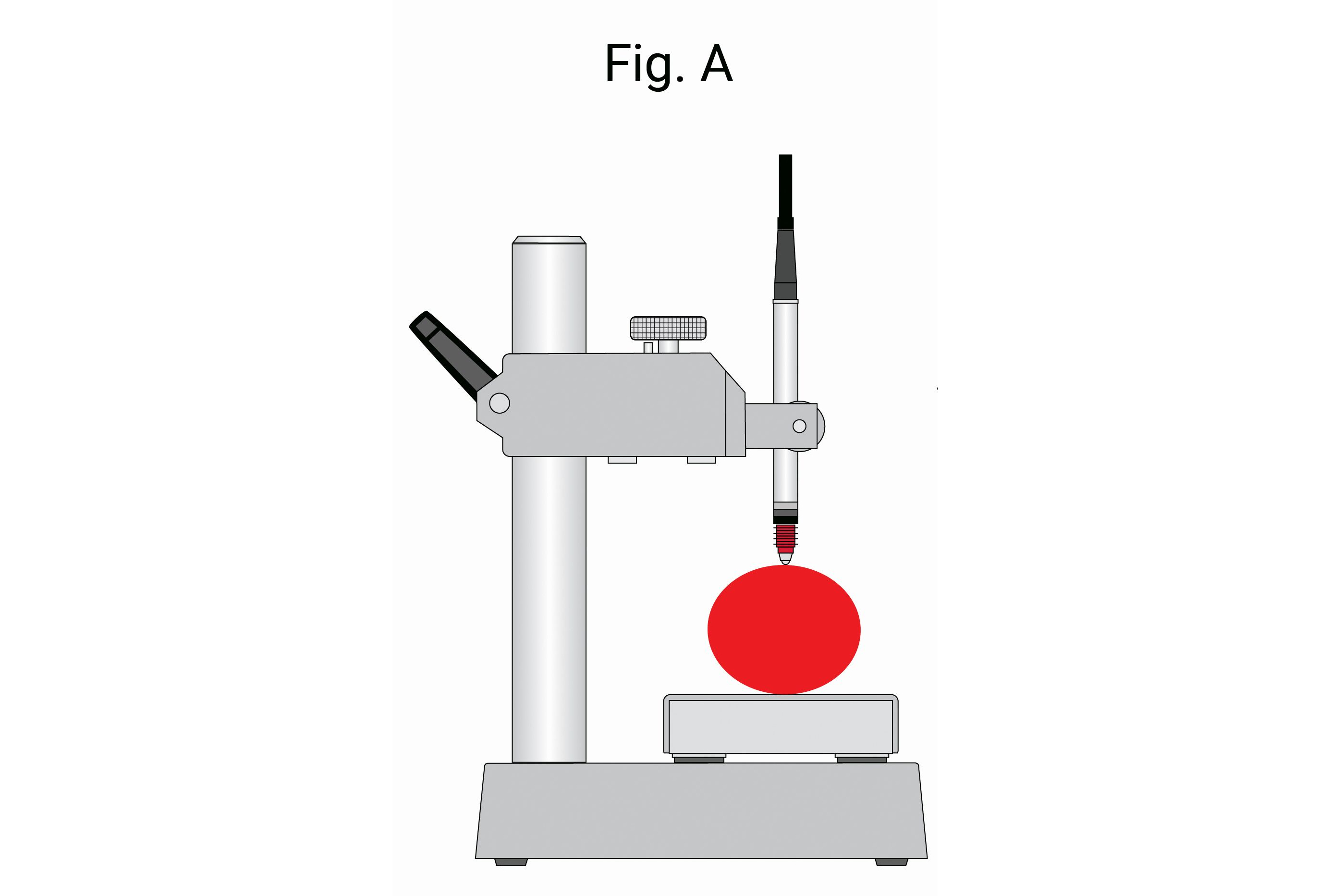
Probably the most practical comparative gage is seen in Fig. A. It offers an interchangeable platen, a long post with an adjustable arm over its full length and a fine adjustment mechanism to set the probe to the nominal position. This stand offers great flexibility for a variety of setups. However, with great flexibility comes a source of error (as the word “flex” implies), because each one of these joints (or connections) is a possible source of looseness. With looseness comes repeat errors that can be shown on the high-resolution display.
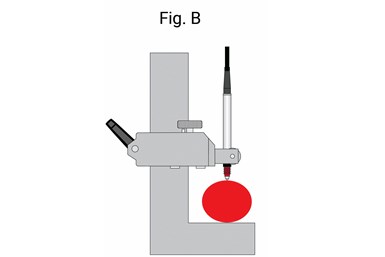
By eliminating the points of concern and making minor changes, gaging performance will improve. In Fig. B, we have made the base and the post into one piece, eliminating two contention points: the moveable anvil and the post connection. This configuration still allows a longer adjustment to accommodate different sizes and fine adjustment of the probe. These are two key factors when a wide range of parts need to be checked.
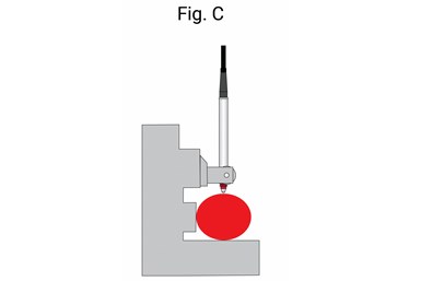
The higher the resolution, the more critical part positioning becomes. In Fig. C, two changes have been made. First, the long-range adjustment has been removed with the retention of the fine adjustment for probe positioning, and a backstop has been added. When mastering any comparative instrument, it is best to master with the same shape master as the part. Adding the backstop ensures the master and the part are positioned at nearly the same location. This arrangement offers only one adjustment point: the fine adjustment to further eliminate loose potentials. The addition of the backstop for more repeatable master and part positioning is a significant improvement.
In Fig. D, we have made the stand for the particular size being measured. It is a fixed comparative gage, offering the highest performance for making
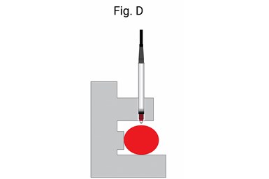
comparative readings. This offers the best opportunity for the most accurate and repeatable results. The only issue that comes to mind with this type of gage is that it is primarily useful in a bench gaging operation. It relies on gravity to hold the part in position. If used as a portable gage, the operator would have to ensure the gage is carefully loaded on the part, so it rests securely on the anvil and the backstop. As one can imagine, this inserts another source of error — the user. Human nature is known to be a large source of measurement errors.
Finally, the solution shown in Fig. E offers the best fit for applications where
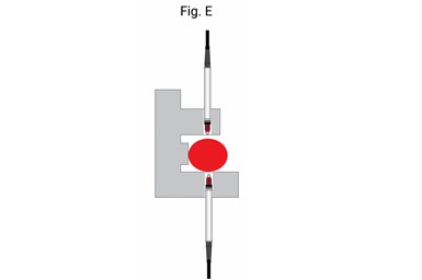
bringing the gage to the part is required. This is the concept that most air or electronic snap gages are built to as they are made to the specific dimension to be measured and employ differential gaging. Differential gaging allows for high-performance length measurement while compensating for a slight shift in line positioning of the part. With these fixed-size variable gages, all the operator must do is ensure the part is locked in against the backstop so the true diameter of the part is displayed as compared to the master.
Adding high-precision resolution, display and probe systems to existing gaging is a logical way to attempt to get more precision from existing gaging. However, it is important to understand that there may be obstacles in the existing gaging that will limit its performance.


Related Content

6 Machine Shop Essentials to Stay Competitive
If you want to streamline production and be competitive in the industry, you will need far more than a standard three-axis CNC mill or two-axis CNC lathe and a few measuring tools.
Read More
4 Ways to Establish Machine Accuracy
Understanding all the things that contribute to a machine’s full potential accuracy will inform what to prioritize when fine-tuning the machine.
Read More
How To Calibrate Your Calipers
If you’re interested in calibrating your own digital, dial or Vernier calipers, here are some steps to take to make sure it goes off without a hitch.
Read More
Ballbar Testing Benefits Low-Volume Manufacturing
Thanks to ballbar testing with a Renishaw QC20-W, the Autodesk Technology Centers now have more confidence in their machine tools.
Read MoreRead Next

The Cut Scene: The Finer Details of Large-Format Machining
Small details and features can have an outsized impact on large parts, such as Barbco’s collapsible utility drill head.
Read More
3 Mistakes That Cause CNC Programs to Fail
Despite enhancements to manufacturing technology, there are still issues today that can cause programs to fail. These failures can cause lost time, scrapped parts, damaged machines and even injured operators.
Read More
