
Making the Most of Rotary Axes
Shops new to advanced rotary machining are sometimes held back by fundamental misunderstandings.

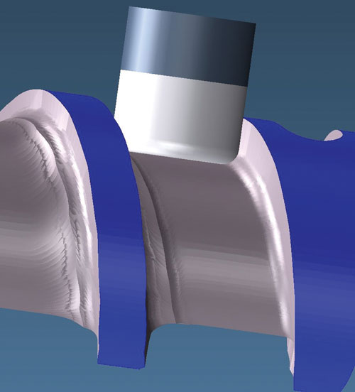
Two-axis-style, analytic cutting can produce final forms in a single pass.
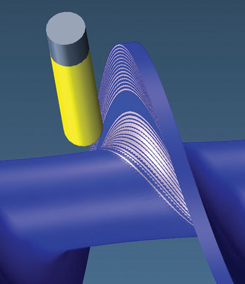
In contrast to analytic tool paths, three-axis-style, single-point-of-contact cuts rely on multiple, successive passes and often require secondary finishing operations to bring the feature to spec.
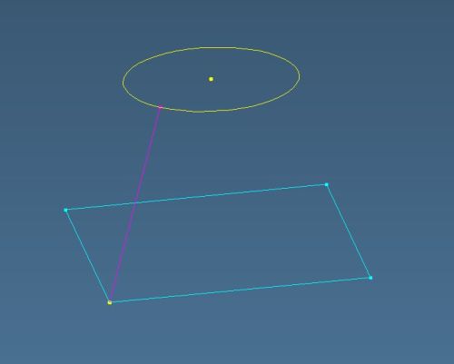
Construction of a ruled surface can begin by arranging two shapes, such as this square and circle, in parallel planes, as shown here. To create the surface, the vertical line sweeps around the perimeter of each shape.
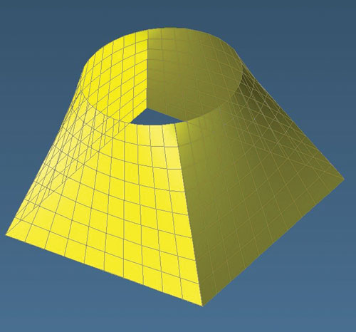
The vertical lines visible on this ruled surface are perfectly straight. This might lead some to believe that the shape could be cut analytically using the side of the tool.
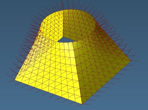
However, the normal vectors—depicted here as lines protruding away from the surface—point in different directions. Any tool used to cut this shape would have to be offset according to these vectors. Thus, analytic cutting with the side of the tool is impossible.
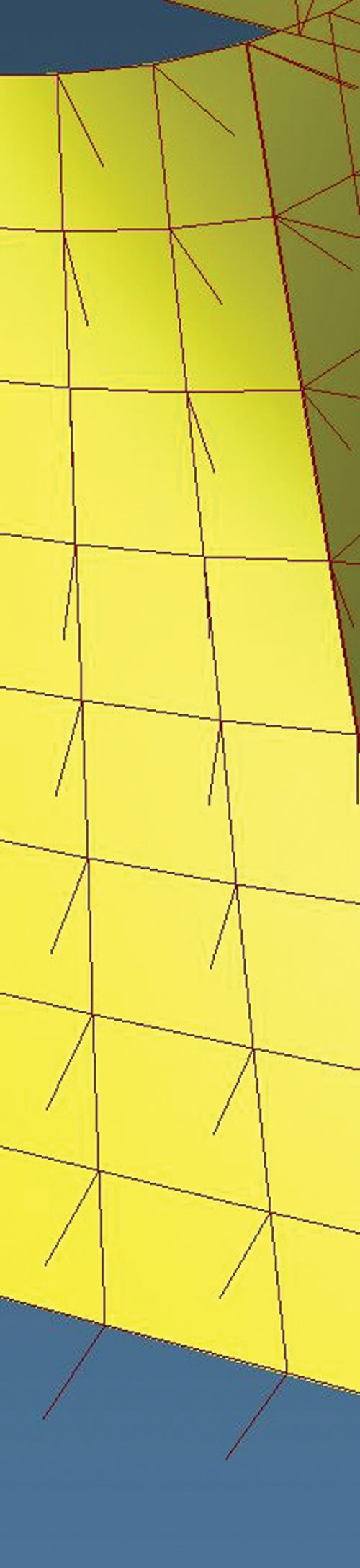
A closer look at the normal vectors.


Shops new to rotary-axis operations—and even a few veterans—often miss opportunities for cutting parts faster and more cost-effectively. However, developing a better understanding of two fundamental issues can help any manufacturer ensure that its four- and five-axis machine tools are achieving their full potential.
So says Bill Gibbs, president of GibbsCAM software developer Gibbs and Associates (Moorpark, California). The first issue he cites involves mathematical principles that govern the tool’s interaction with the workpiece during rotary operations. The second involves the difference between cutting a part to exactly match a solid model and giving customers what they want.


Keeping It Simple
The first problem is somewhat ironic in that it relates to a concept that most machinists understand intuitively. That is, the advantage of what Mr. Gibbs calls an “analytic” tool path. This term describes a tool path that precisely follows the workpiece geometry and uses the side of the cutter to produce finished features in a single pass.
To explain, he offers this hypothetical situation: Two shops using identical machines and software are asked to cut a piece of metal into a simple cylindrical shape. One chooses to use two-axis toolpath functions, and the other chooses to use three-axis toolpath functions. Which will cut the part faster and more cost effectively?
The shop using two-axis functions will win every time, Mr. Gibbs says. That’s because two-axis tool paths can use the side of an end mill to produce the finished wall of the cylinder in a single, circular motion. In contrast, three-axis motion relies on a single, tangent point of contact between the tool tip and the workpiece to cut the cylinder in multiple, successive passes that approximate the part surface within a specified tolerance. This strategy results in unnecessary complexity—more lines of code, longer cycle times, ridges that must be removed via secondary operations, and so on—and a less-efficient machining operation.
Although he admits this explanation is overly simplified, Mr. Gibbs says most machinists and programmers instinctively grasp the distinction between these two types of tool paths. In fact, they often spend much of their time coming up with clever ways to cut parts with tool paths that are as close as possible to the basic two-axis ideal described above. The same concept applies regardless of how many axes of motion are available on the machine being programmed. “There are parallels—you can do milling with a rotary axis that is equivalent to two-axis milling or equivalent to three-axis milling,” Mr. Gibbs explains. “Just as these tool paths are hugely different in the three-axis world, they are hugely different in the rotary milling world.”
However, many machinists and programmers who are new to rotary operations run into difficulty determining whether a part should be cut with the equivalent of a two-axis-style, analytic strategy or a three-axis-style, single-point-of-contact strategy. While the same concepts that apply to operations on a three-axis machine also apply here, introducing rotary axes creates a new layer of complexity, Mr. Gibbs says.
Unbreakable Rules
In GibbsCAM, the module that provides the rotary equivalent of two-axis, analytical milling is called Radial Milling, which drives one rotary axis and three linear axes and is designed to work from wireframe geometry. Consider a three-axis VMC with a fourth-axis rotary table. With Radial Milling, a user can rotate a part continuously while cutting with the side of the tool to achieve an analytic tool path, one akin to the two-axis tool path used to cut the cylinder in the above example. In theory, this would produce the part the user desires.
The key phrase here is “in theory.” Some parts are simply impossible to cut this way, even with rotary axes. One of the most common points of confusion involves parts constructed via one of the surface types designers use most often: the ruled surface. A ruled surface, Mr. Gibbs explains, can be constructed by taking two shapes in parallel planes and connecting them via a straight line. That line sweeps around the perimeter of both shapes to create the surface. For example, one of the simplest ruled surfaces, a cylinder, is constructed by sweeping a straight line around the perimeters of two parallel-plane circles.
These surfaces can get much more complicated than a simple cylinder, but according to the very definition of a ruled surface, a straight line can fit precisely at every position on its perimeter. Many programmers assume they ought to be able to cut these shapes analytically using the side of a tool. As they discover when parts come back out of tolerance, this is impossible for all but the simplest ruled surfaces. The reason is that the tool must be offset from the workpiece along a “normal”—or perpendicular—vector, Mr. Gibbs explains.
As an example, he cites a ruled surface drawn between a square and a circle in offset parallel planes. Such a shape would appear square at one end, circular at the other, and somewhere between a circle and square throughout the middle. “Picture the normal vectors as little arrows pointing perpendicularly away from the straight lines that make up the surface. The vector at the top of the straight line points in a different direction than the one at the bottom. One wants to push the tool off in one direction, and one wants to push it off in a different direction. There’s no way to cut this surface perfectly with the side of the tool.”
In cases such as this, the programmer would be better off using GibbsCAM’s five-axis module. This is the software’s rotary equivalent of three-axis techniques—that is, machining via a series of passes with a single tangent point of tool contact. While not as ideal as a purely analytic tool path, using a large-diameter cutter and employing rotary axes to continually adjust the tool’s angle can enable taking wide, sweeping cuts that provide efficient machining while staying within specified tolerances.
However, many shops don’t realize that they might not need to stay within tolerances specified in a solid model, Mr. Gibbs says. “It’s a misconception to think that all parts are perfectly defined in their solid models, and that if they’re machined to some tolerance, then everyone will get what they want,” he explains. “The important thing is to give customers what they want, not necessarily what they put in the CAD file.”
Breakable Rules
In other words, shops should consider the function of any given part when planning how it will be machined, Mr. Gibbs says. Just because the CAD file denotes a specific tolerance for a given feature doesn’t mean that the part will malfunction if that tolerance isn’t met. That’s especially true if the solid model is imprecise. Shops should take steps to develop an understanding of which part features are critical and which are not. Those that do—usually those that have developed expertise in some specific family of parts—are typically best at meeting customer delivery targets, minimizing manufacturing costs and winning repeat contracts, Mr. Gibbs says.
In the arena of rotary machining, feed screws provide a good example of this, Mr. Gibbs says. These are long parts with deep grooves used in extruders, meat grinders, plastic injection molding machines and other equipment. Their twisted, helical shape makes them ideal candidates for production on machines with rotary axes. While these parts can be quite a challenge to machine, they are typically not as complicated as they look, Mr. Gibbs says.
That’s because the functionality of most feed screws is affected by relatively few key dimensions—diameter measurements, groove widths and the size of the ridges between the grooves, among others. In fact, some feed screw designers still use 2D drawings, and many such drawings don’t contain enough information to construct a solid model. Once translated to a solid model, more dimensions and surfaces must be specifically defined, even those that aren’t important to the function of the part. “A solid model implies you care about everything,” Mr. Gibbs says.
As a result, a shop that isn’t familiar with feed screws might decide to apply GibbsCAM’s five-axis functionality in order to machine the part exactly as it appears in the solid model. The result is a lengthy, costly machining process—and perhaps a lost bid. Meanwhile, across the street, another shop more familiar with feed screws bases its quote on the use of GibbsCAM’s Radial Milling module to achieve analytic cutting with the side of the tool. Rather than using thousands of toolpath segments and time-consuming finishing operations like its competitor, the latter shop machines the screw using arcing, helical cuts that leave a smooth surface and final shape on the first pass.
Understanding the Customer, Part and Process
It’s also possible that the latter shop had no previous experience with feed screws. Perhaps it just took the time to consult with the customer and develop a deeper understanding of the customer’s needs and what it wanted out of that specific part. That would seem like an obvious thing to do, but it can’t be emphasized enough, Mr. Gibbs says.
Regardless, the shop did have another advantage that might have been harder to come by—the ability to determine whether that particular part would be better machined via single point-of-contact, three-axis-style tool paths, or analytic, two-axis-style tool paths. “As you come to better understand how the side of a tool relates to surfaces, rotary machining gets easier and easier,” Mr. Gibbs concludes.


Related Content

Building an Automation Solution From the Ground Up
IMTS 2022 provides visitors the opportunity to meet with product experts to design automation solutions from scratch.
Read More
A New Milling 101: Milling Forces and Formulas
The forces involved in the milling process can be quantified, thus allowing mathematical tools to predict and control these forces. Formulas for calculating these forces accurately make it possible to optimize the quality of milling operations.
Read More
Understanding Swiss-Type Machining
Once seen as a specialty machine tool, the CNC Swiss-type is increasingly being used in shops that are full of more conventional CNC machines. For the newcomer to Swiss-type machining, here is what the learning curve is like.
Read More
How to Reduce Cycle Times by 70% and More on Your Existing CNCs and Dramatically Improve Tool Life Too
By employing advanced high efficiency milling techniques for the entire machining routine, SolidCAM’s iMachining technology can drastically reduce cycle times while vastly improving tool life compared to traditional milling.
Read MoreRead Next

The Cut Scene: The Finer Details of Large-Format Machining
Small details and features can have an outsized impact on large parts, such as Barbco’s collapsible utility drill head.
Read More

3 Mistakes That Cause CNC Programs to Fail
Despite enhancements to manufacturing technology, there are still issues today that can cause programs to fail. These failures can cause lost time, scrapped parts, damaged machines and even injured operators.
Read More