
Standard Jobs Beyond Standard Speed
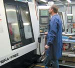
This job shop is defining the role of extremely high spindle speed in variable-volume, variable-part-number production.
.jpg;width=70;height=70;mode=crop;format=webp)


From Fluke Metal's perspective, here are two important features of the high-rpm machines. Five-axis positioning capability lets the shop machine certain multi-face parts complete in one setup. And non-contact tool measurement is particularly valuable for the work with tiny tools. When tools measure 0.010 inch in diameter, it can be difficult to confirm visually that there is even a tool in the holder!
Nesting is an important component of Fluke Metal's process for machining the part more efficiently. The shop says high rpm levels tend to strengthen the case for machining multiple pieces per cycle.
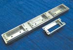
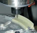
This aluminum part, formerly machined on more standard machining centers, is now produced more efficiently on one of the high-rpm machines.

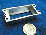
At top is a detail of another plastic part machined at Fluke Metal. Each of these 0.120-inch-long pockets consist of a 0.024-inch square section mated to a "tail" 0.018 inch wide. In the magnified video image on the bottom, a dime is laid over one of the square sections for scale. The dime covers the right side of the square-shaped hole. The bumps seen in shadow are the dime's serrations.
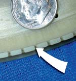
The 0.014-inch-diameter hole meets a 0.017-inch deep milled pocket that becomes visible only under magnification.

From Fluke Metal's perspective, here are two important features of the high-rpm machines. Five-axis positioning capability lets the shop machine certain multi-face parts complete in one setup. And non-contact tool measurement is particularly valuable for the work with tiny tools. When tools measure 0.010 inch in diameter, it can be difficult to confirm visually that there is even a tool in the holder!

At top is a detail of another plastic part machined at Fluke Metal. Each of these 0.120-inch-long pockets consist of a 0.024-inch square section mated to a "tail" 0.018 inch wide. In the magnified video image on the bottom, a dime is laid over one of the square sections for scale. The dime covers the right side of the square-shaped hole. The bumps seen in shadow are the dime's serrations.

The 0.014-inch-diameter hole meets a 0.017-inch deep milled pocket that becomes visible only under magnification.
The proven, highly profitable production applications of the fastest metalworking spindles all tend to have one thing in common: infrequent tool changes. High speed finish milling of a mold core or cavity may keep the same tool cutting for an hour or more . . . and high speed milling of an aluminum aircraft component may cut the complete form out of a solid block using one tool alone. Though a very fast spindle can increase chip-to-chip toolchange time, that doesn't matter much in applications like these.
But applications like these aren't typical. Most of the parts that most shops machine call for a larger number of tools per part and less machining time for each tool. Do the fastest spindles make sense in these shops as well?


In other words, can a 30, 40 or 50,000-rpm spindle perform well in small- to medium-volume batch machining?
The answer—at least in one shop's experience—is a qualified yes.
Fluke Metal Products is a job shop in Bothell, Washington. The shop has 18 CNC machines. The two newest machining centers are a pair of high-precision verticals capable of 50,000 rpm. The machines represent a considerable leap forward for the shop, whose previous top speed was 15,000 rpm. Fluke Metal bought the machines specifically to mill and drill fine-detail electronics parts using tiny tools that practically demand the high speed. However, in the process of machining these parts, the shop learned a great deal about how to use such high spindle speed effectively.
Now, shop personnel have begun to look to the more typical job shop work in search of other parts that can also be run much more productively on these machines.
Not every part is a good candidate. Not even most of the shop's parts are good candidates.
But even so, Fluke Metal is discovering that a significant fraction of its batch production work on machining centers probably does lend itself to a much higher rpm. The potential to run these particular parts much faster—combined with the shop's growing ability to identify which parts these are—promises to make machining near 50,000 rpm an important addition to the shop's list of capabilities.
Details
A part that demands the high speed is shown in photos (below right and below left). Parts such as this account for much of the shop's fine detail work. Machined from G10 plastic, the part is a vacuum fixture that holds small electronics components in place during an automated inspection process. Among the machined features is a tiny vacuum port at the bottom of each milled slot. Configurations vary, but a representative version of this port consists of a 0.014 by 0.047 inch pocket measuring 0.017 inch deep, in the floor of which is a 0.014-inch diameter hole that penetrates 0.360 inch to exit the bottom face of the part. The pocket is milled using a 0.010-inch diameter end mill. The hole is drilled from the top of the slot, meaning this slender tool has to extend more than half an inch to provide clearance and complete the hole.
Features like these are so small that optical magnification presents the only practical way to inspect them.
And the tools used to machine these features are so small that only an extremely high rpm can deliver a productive sfpm.
Fluke Metal first tried to achieve this speed using "speeders," or spindle speed increasers—essentially toolholders with gearboxes built in. Speeders let the shop get to 45,000 rpm on standard machining centers, but the cut wasn't smooth enough. Vibration and runout caused the process to break tolerance too often, and also to snap the slender, expensive tools far too frequently. The shop decided to find a more stable platform for high-rpm work.
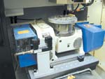
The machines it chose are Vibra-Free machining centers from Compumachine (Wilmington, Massachusetts). Developed primarily for close-tolerance hard steel milling and graphite electrode milling in mold shops, this machine model was designed for high stability and high rigidity. Its spindle, supplied by Ibag (North Haven, Connecticut), cuts quietly at 45,000 rpm. This is the speed at which the shop typically runs these machines.
Taking advantage of the capacity for smooth cutting at very high speeds and feed rates made the shop steadily more productive at producing the electronics parts. An accessory made the shop more productive still. Fluke Metal's second high-rpm machine came with an indexing rotary table for fourth- and fifth-axis positioning. This addition allowed the vacuum fixture parts to be machined entirely in one setup. The shop was ready to begin asking what else it could run on these machines.
The first part to make the transition is pictured (below right). This aluminum part used to be machined productively on a standard machine. Now it's machined much more productively on a much faster machine.
HSM In Action
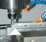
The way this part is now produced provides a classic example of machining more effectively by taking faster, lighter cuts.
Light cuts are a physical necessity for such a fast machine. Spindle power (12 hp peak) is comparable to what might be found on a slower standard machine, but power is the product of torque and speed. If motor power remains constant for a spindle offering a higher rpm, then the associated cutting torque can only be less. Depth of cut therefore goes down.
However, metal removal rate goes way up, because the increase in feed rate more than offsets the lighter cut. The aluminum part used to be milled at 18 ipm, but now—while depth of cut has been reduced by two-thirds—the feed rate through straight parts of the cut has been raised to 300 ipm.
The lighter cuts also improve quality. With less force in the cut, the shop finds it's now less common for the part's thin walls to warp. High speed machining thus makes the process more consistent and reliable.
Fluke Metal is no stranger to these techniques. When the shop advanced from 8,000 to 15,000 rpm, that move involved a similar transition. The 50,000-rpm machines push fast, light cutting to a farther extreme. And this extreme is not universally better for all machining center work.
Shop general manager Larry Fluke describes the characteristics of a job that does make sense on these fast machines.
He says it's particularly significant that the aluminum part is milled from a solid block instead of from a casting. For more reasons than one, that trait accounts for why high speed machining can produce the part so effectively.
What Parts Work
When a part does not require the use of tiny cutting tools, says Mr. Fluke, the main characteristic that indicates the part may be a good fit for the fastest machines is long machining time between tool changes.
Machining time doesn't have to be nearly as long as that of the mold or aircraft part mentioned at the beginning of this article. However, it does have to be long enough for faster metal removal to have a chance to make up for the increase in chip-to-chip toolchange time.
The size of this increase may vary. In Fluke Metal's case, the difference is generally 30 seconds per tool. The spindle at 45,000 rpm is subject to centrifugal force far in excess of what a spindle sees at some fraction of that speed. And though the spindle is thermally stable, Mr. Fluke believes the difference in temperature between the spindle and a cold toolholder may be significant. Because of factors such as these, personnel at Fluke Metal allow time for newly loaded toolholders to "seat" within the spindle. The shop's standard practice is to insert a 30-second dwell after every tool change during high-rpm, high-precision machining to make sure the toolholder settles in.
Parts machined from solid can be produced efficiently despite this delay because these parts require a relatively large amount of stock to be removed using a small number of tools. This is one reason why machining from solid favors the faster rpm.
But another reason is that machining from solid makes it inherently easier to amortize each tool change by machining multiple pieces per cycle.
When a part is machined from solid, machining multiple pieces simultaneously doesn't have to involve the expense of multiple setups. All that's required is for the same part to be nested multiple times within a larger blank that's set up only once.
Fluke Metal takes precisely this approach to machining the aluminum part, milling three pieces per cycle out of a single block. This same technique was sometimes used when the part was produced on slower machining centers, but higher rpm increases its effectiveness. Each tool in the cycle can machine the same feature three different times, meaning the same number of tool changes can be divided across a larger number of units.
By stretching out the amount of stock removal between tool changes, nesting can make a good high-rpm job out of a part that otherwise wouldn't entail enough machining for the high speed machines to be effective. As the shop shifts more part numbers onto these machines, says Mr. Fluke, nesting is certain to become an even more common practice for the shop than it already is today.
He adds that there is something else about a high speed spindle that also determines what parts are suited to it. The spindles don't lend themselves to rigid tapping capability. As a result, along with long cutting times and/or a small number of tool changes per part, the lack of any tapped holes joins the list of what characteristics make for a good high speed machining part.
These characteristics will help determine which of Fluke Metal's existing jobs will be shifted to the high-rpm machines.
As for how to machine these jobs as effectively as possible on the fast machines, that knowledge will come in time. Such was the case with the electronics parts. Much of what the shop now knows about using high spindle speeds effectively came from its own experience. And much of that experience relates to cutting tools. When the shop first started working at the higher rpm, says Mr. Fluke, there were some surprises related to tooling.
Learning By Doing
One surprise was simply the size of the tooling investment. Making use of the high-rpm machines required not only the small cutting tools needed for the fine detail work, but also the high-quality, well-balanced toolholders and collets essential for smooth cutting with tools of all sizes at the higher speeds. The shop quickly came to realize that it would need a larger-than-expected tooling outlay in order to unlock all the effectiveness of the new machines.
Mr. Fluke says another surprise was to discover how little information is available about effective use of cutting tools at the speeds the shop now achieves.
"There wasn't much the cutting tool companies could tell us," he says. "We had to find out for ourselves."
Much of what the shop has learned relates to controlling chatter. For example, in some cases where a carbide cutting edge is too round for the particular application, a high speed steel cutting edge can be so sharp that it chatters excessively. To quiet the cut, the shop has taken to honing its own radii onto some HSS tools.
In other cases, the shop has brought chatter under control by switching from a two-flute end mill to a three-flute tool. A likely reason why this works is that the high-rpm cutting has brought the frequency of cutter impacts into a range where there are "sweet spots" that make the process more stable—a phenomenon that isn't so pronounced at lower speeds. At the high frequency level, adding another flute may change the frequency of cutter strikes to a value matching a sweet spot—a frequency at which the process harmonizes and chatter goes down.
Winning knowledge like this takes time, Mr. Fluke says. In fact, due to the need for experimentation, it often takes open time on the machine. Fluke Metal made a significant investment to achieve its current level of high speed machining capability. And because the shop continues to devote resources to learning how to use that capability effectively, this investment is still ongoing.


Related Content

How to Accelerate Robotic Deburring & Automated Material Removal
Pairing automation with air-driven motors that push cutting tool speeds up to 65,000 RPM with no duty cycle can dramatically improve throughput and improve finishing.
Read More
YCM Alliance Hits IMTS
YCM Technology has joined with other like-minded machine tool manufacturers to take a solutions-based approach to manufacturing.
Read MoreRead Next

3 Mistakes That Cause CNC Programs to Fail
Despite enhancements to manufacturing technology, there are still issues today that can cause programs to fail. These failures can cause lost time, scrapped parts, damaged machines and even injured operators.
Read More

The Cut Scene: The Finer Details of Large-Format Machining
Small details and features can have an outsized impact on large parts, such as Barbco’s collapsible utility drill head.
Read More