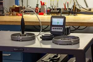
Gaging Countersunk And Chamfered Holes
While countersunk and chamfered holes are similar in appearance, functionally they are quite different. Consequently, different gages exist to serve these different functional requirements.
While countersunk and chamfered holes are similar in appearance, functionally they are quite different. Consequently, different gages exist to serve these different functional requirements.
Hole chamfers are usually specified simply to make it easier to insert a screw, pin, bushing, or other assembly component. The component doesn't bear on the chamfer, so diameter and angle tolerances are usually not critical to the part's performance.
A countersink, on the other hand, is a functional surface upon which a fastener head bears. Because fastener performance is so important, countersink tolerances are critical. The countersinks on an aircraft's skin are an excellent example. If the countersink is too deep, there may be inadequate skin material for the rivet to hold against the underlying frame. If a countersink is too shallow, the rivet head will protrude, increasing air resistance. This latter condition may sound trivial, until you consider the cumulative effect of literally hundreds of thousands of protruding rivet heads on an airplane's skin.
Countersinks tend to be small—usually 0.780 inch or less—and angles are closely controlled: usually 30 degrees, 82 degrees, 90 degrees, 100 degrees, or 130 degrees. Chamfers may be specified at any angle up to 130 degrees and on holes or inside diameters of any size.
Both countersink gages and chamfer gages are usually hand-held instruments, although both can be mounted on bench stands, a convenience if the parts being measured are small. They both perform the measurement by means of a plunger mechanism, but they do not measure the depth to which the angled surface extends into the hole. Rather, they measure the major diameter of the feature—that is, the largest diameter of the hole, where it intersects the top surface of the part. To convert the vertical motion of the plunger into a diameter measurement, the gages require an indicator with a special-ratio movement or readout.
The main difference between countersink and chamfer gages is the configuration of the plunger. Chamfer gages have an angled plunger consisting of three fluted sections. The angle of the plunger must be greater than the angle of the chamfer, to ensure that the plunger contacts the major diameter only. Typically, the range is split in two— from 0 degrees to 90 degrees and from 91 degrees to 130 degrees—so that two gages have traditionally been required to measure the entire range of chamfers. Recently, however, gages with replaceable plungers have been introduced, allowing a single gage to be used with chamfers of any angle. Replaceable plungers also provide flexibility to measure across a larger range of diameters and to switch between ID and OD chamfers.
Because countersinks are more critical, countersink gages have conical plungers that fit closely against the entire surface of the countersink feature. While some slight difference in the angles of the plunger and the countersink is acceptable, there must be a fairly close match between them. There are no replaceable-plunger countersink gages available at this time, so separate gages are required for each angle requiring inspection.
Both types of gages may be mastered against a part master that duplicates the specified chamfer or countersink. Chamfer gages can also be mastered against any certified flat surface. In most cases, this means the gage will perform like an absolute or direct-reading gage, in which case the indicator displays the feature's actual diameter. Alternately, if the chamfer gage has a digital indicator that allows pre-sets to be entered, then it can still be used for comparative (plus or minus from nominal) measurements, even if it is mastered on a flat.
Related Content
4 Ways to Establish Machine Accuracy
Understanding all the things that contribute to a machine’s full potential accuracy will inform what to prioritize when fine-tuning the machine.
Read MoreHow to Choose the Correct Measuring Tool for Any Application
There are many options to choose from when deciding on a dimensional measurement tool. Consider these application-based factors when selecting a measurement solution.
Read MoreDetermining Out-of-Roundness at the Point of Manufacture
George Schuetz, Mahr Inc.’s Director of Precision Gages, offers these techniques for measuring roundness on the shop floor.
Read MoreBallbar Testing Benefits Low-Volume Manufacturing
Thanks to ballbar testing with a Renishaw QC20-W, the Autodesk Technology Centers now have more confidence in their machine tools.
Read MoreRead Next
3 Mistakes That Cause CNC Programs to Fail
Despite enhancements to manufacturing technology, there are still issues today that can cause programs to fail. These failures can cause lost time, scrapped parts, damaged machines and even injured operators.
Read MoreThe Cut Scene: The Finer Details of Large-Format Machining
Small details and features can have an outsized impact on large parts, such as Barbco’s collapsible utility drill head.
Read More


