
.jpg;width=70;height=70;mode=crop;format=webp)
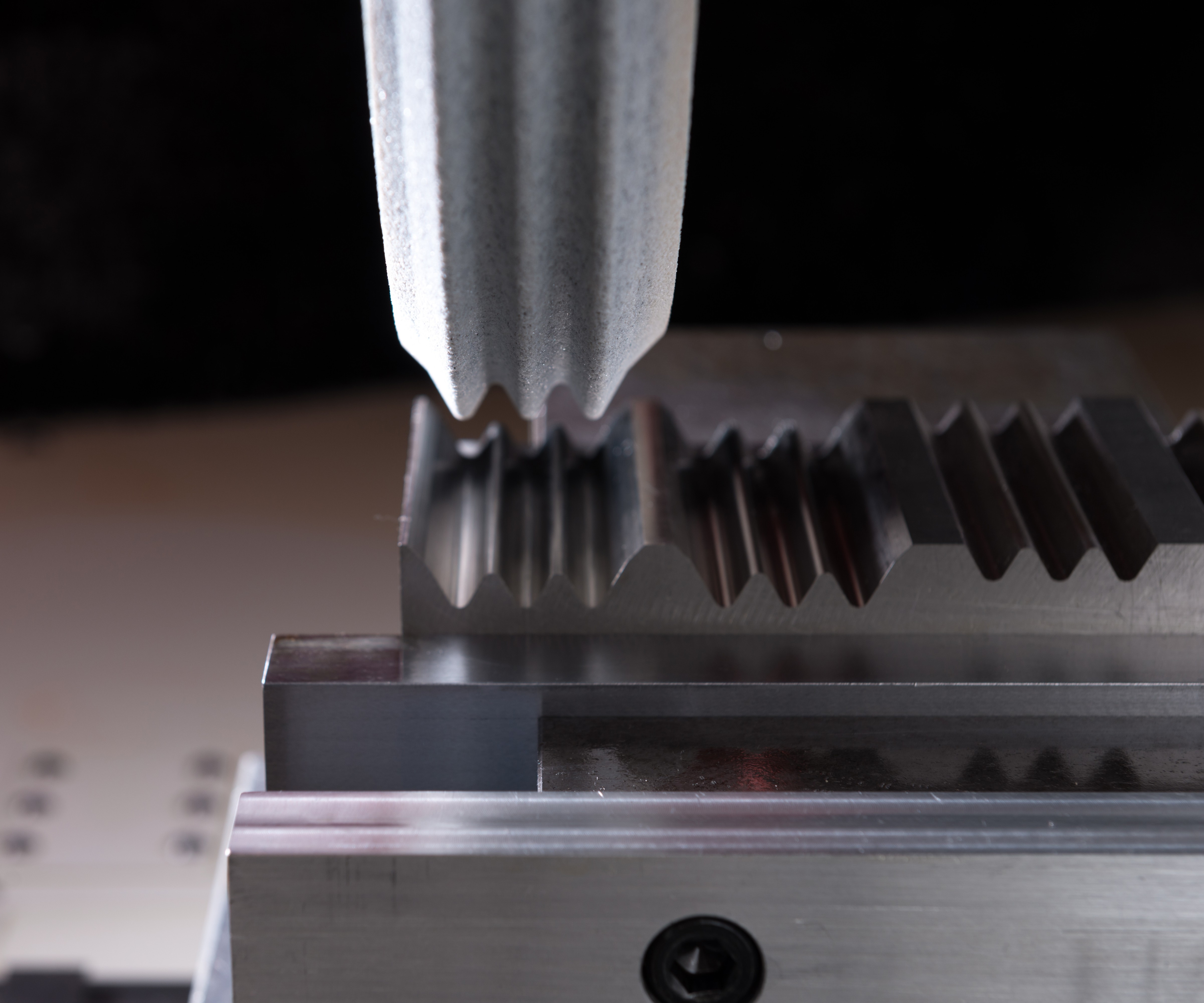
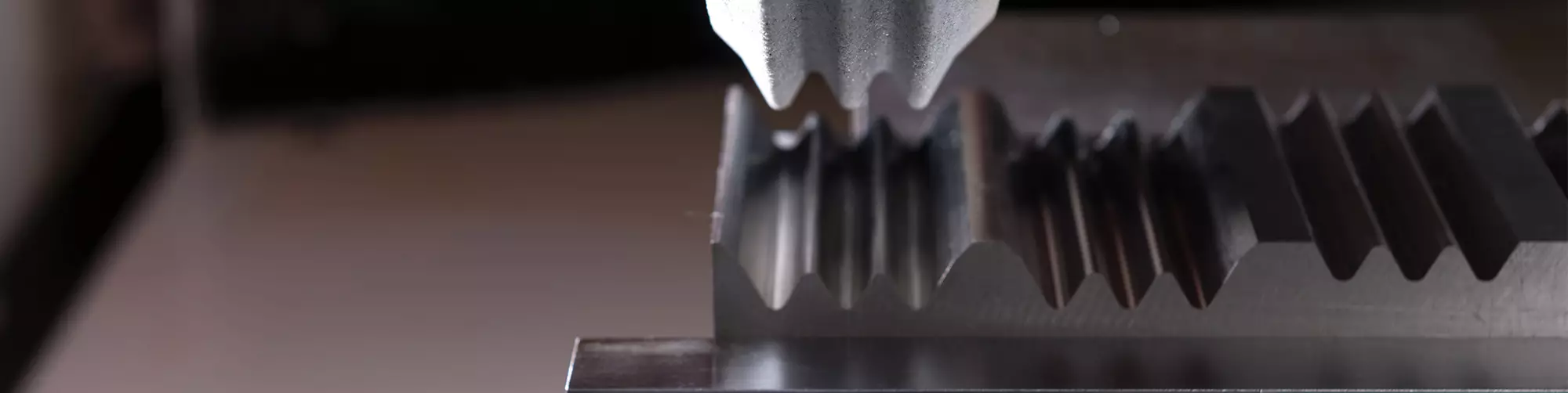
Particularly in hard-to-machine alloys, creep-feed grinding using a profiled wheel offers a way to realize precise forms that would be difficult to generate via any other type of machining.
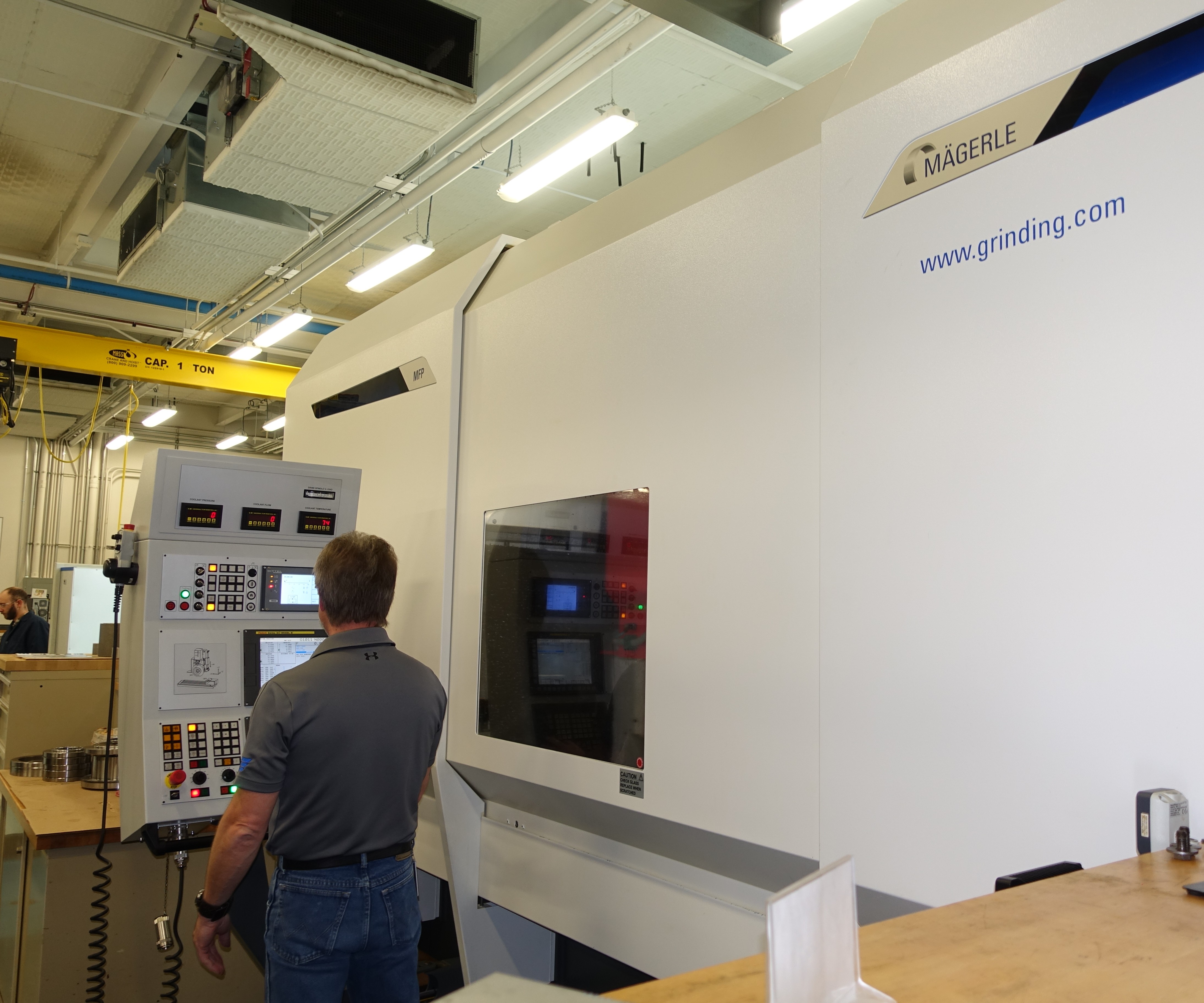
At the Higgins Grinding Technology Center near Boston, one of the machines routinely used for creep-feed grinding research and process development is this one from Mägerle (also seen in the previous photo).
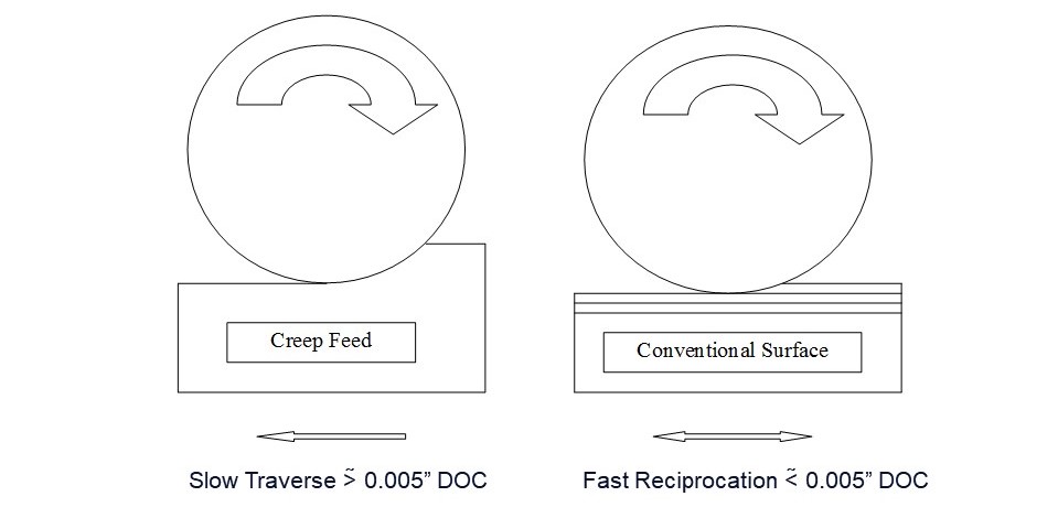
What is creep-feed grinding? Compared to surface grinding, it has a higher depth of cut and slower traverse rate. Norton Saint-Gobain places the minimum depth of cut for creep-feed at 0.005 inch, but others imagine the starting point for creep-feed to be deeper than this.
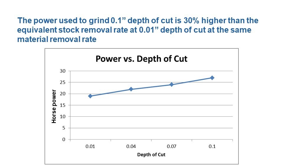
Creep-feed grinding is a high-force process. A heavier depth of cut demands higher horsepower for the same material removal rate.
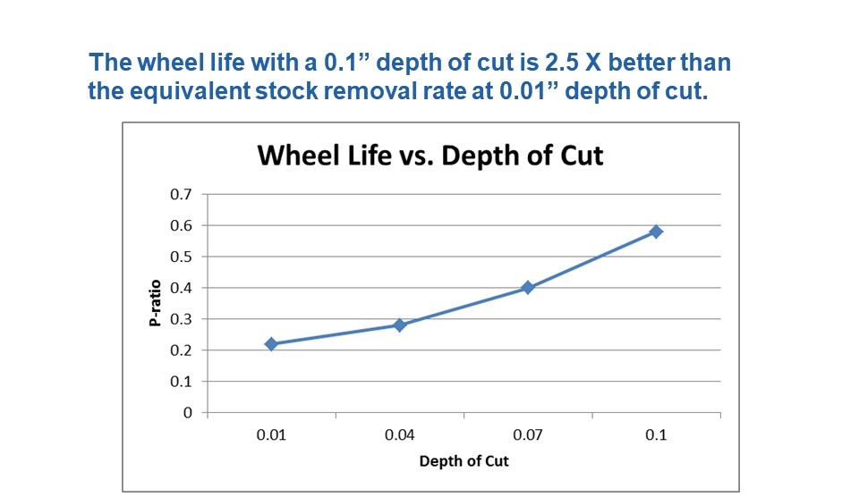
Still, grinding deeper tends to extend the life of the wheel. “P-ratio” describes stock removed per circumferential inch of the wheel. This graph describes the performance of a single-layer-plated CBN wheel.
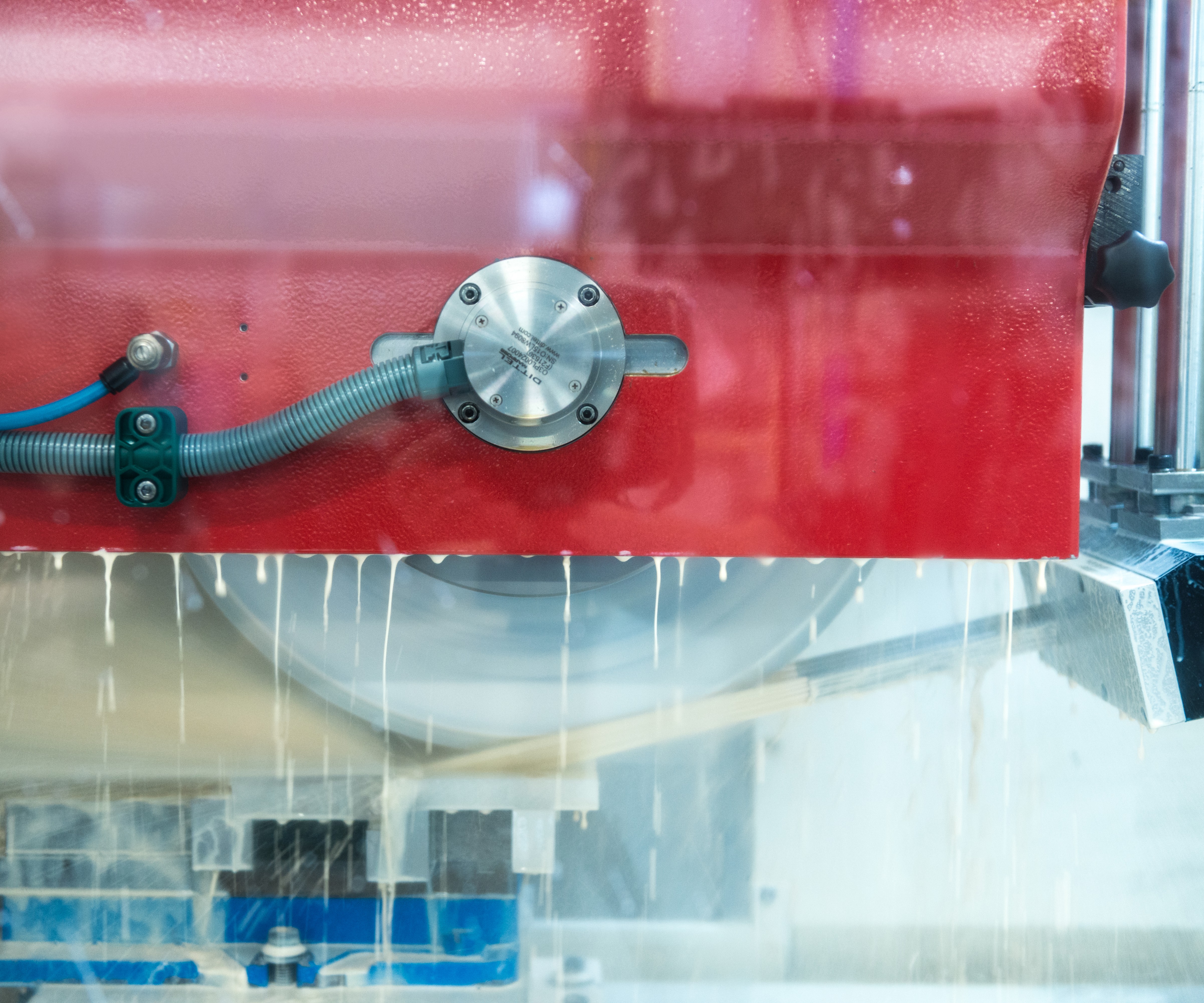
Coolant is vital in creep-feed grinding. One potentially valuable consideration is matching the coolant-flow speed to the speed at the surface of the wheel.
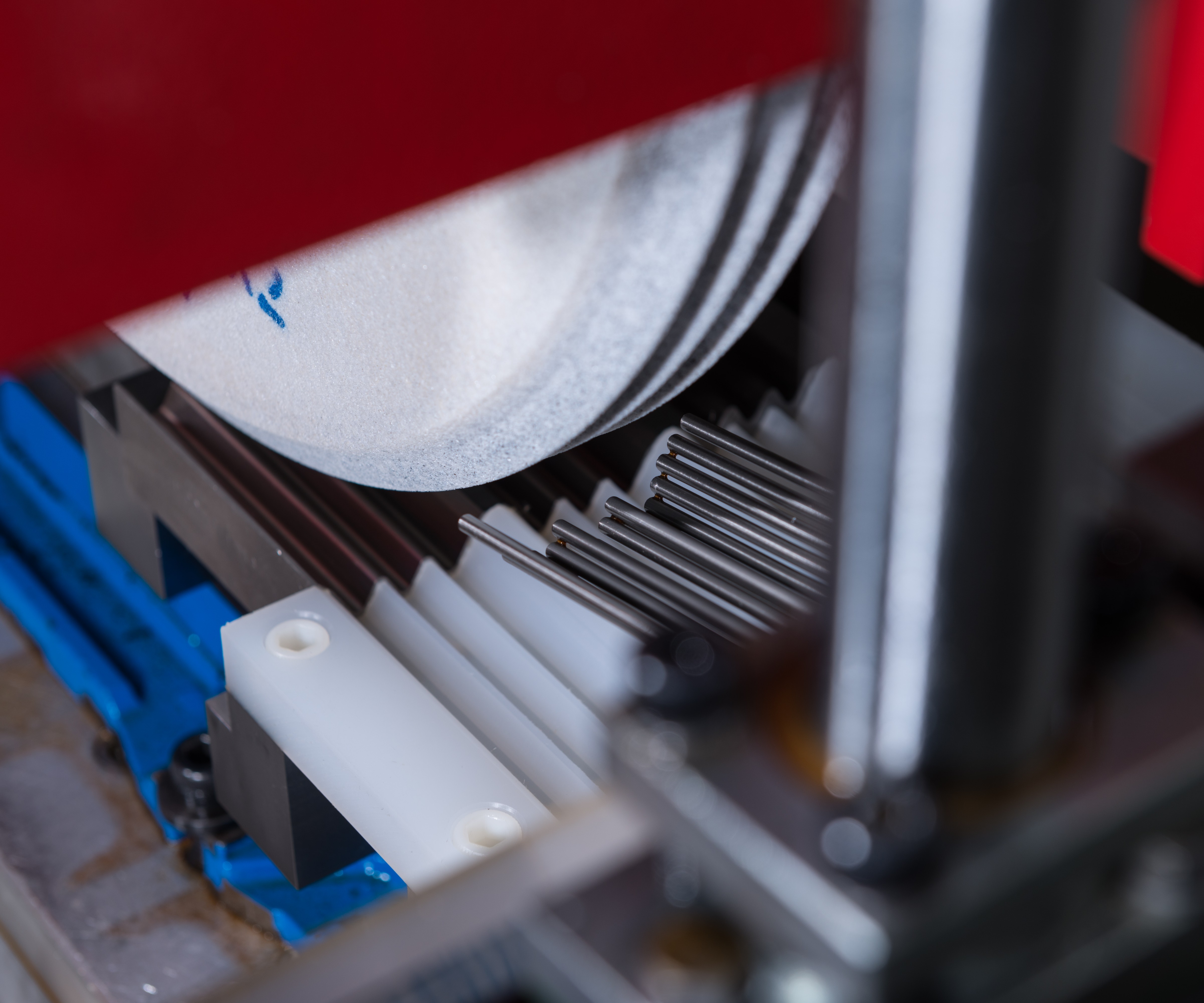
Another consideration for maximizing the effectiveness of coolant in creep-feed grinding: Coolant nozzles arranged to follow the profile of the wheel.
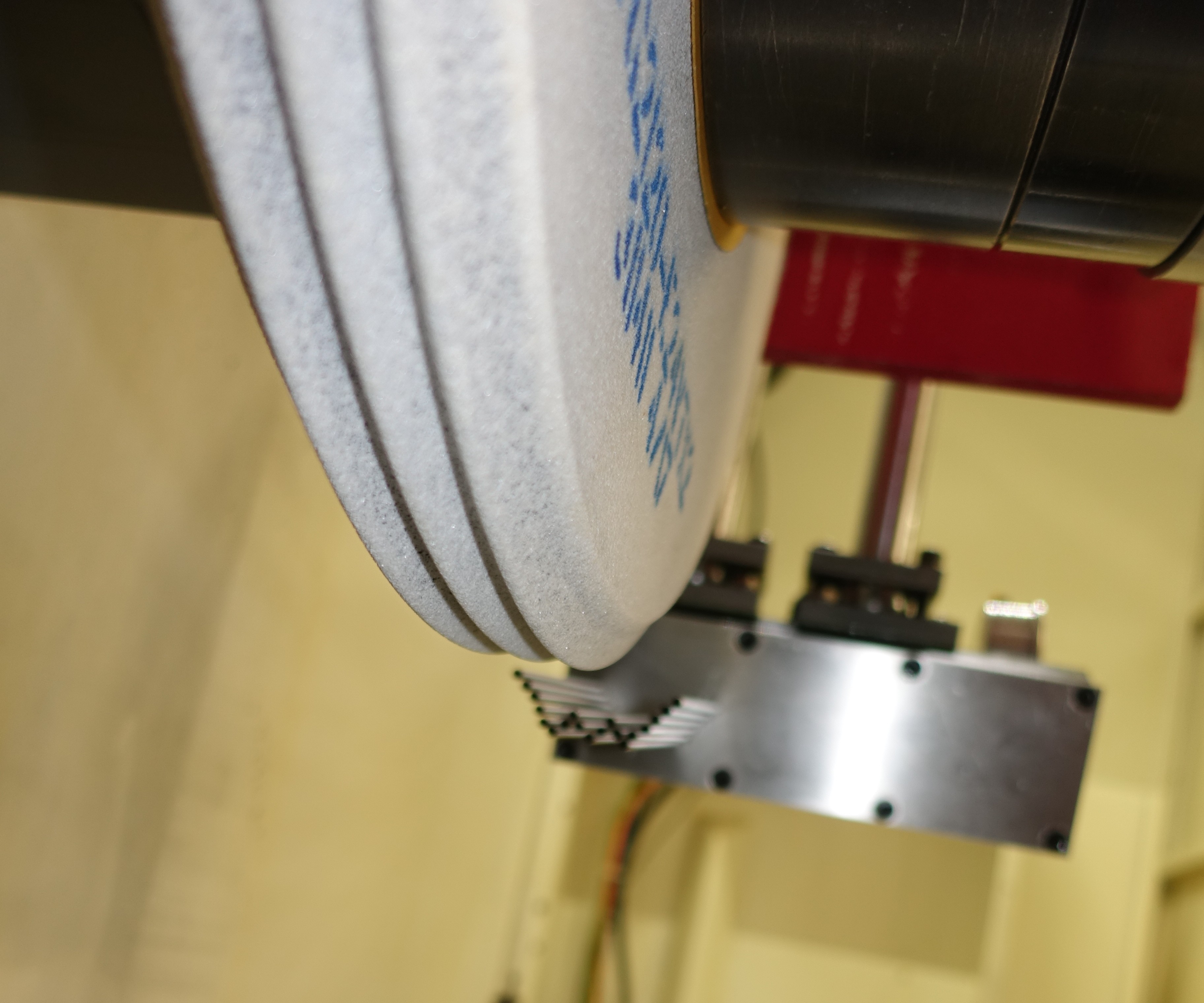
Here is another view more clearly showing the array of coolant nozzles matching the wheel’s profile.

For creep-feed grinding with the aim of productive material removal rates, down grinding is the preferred choice. In the heaviest-cutting applications, the alternate approach subjects the wheel to friction and heating before it begins to remove material.
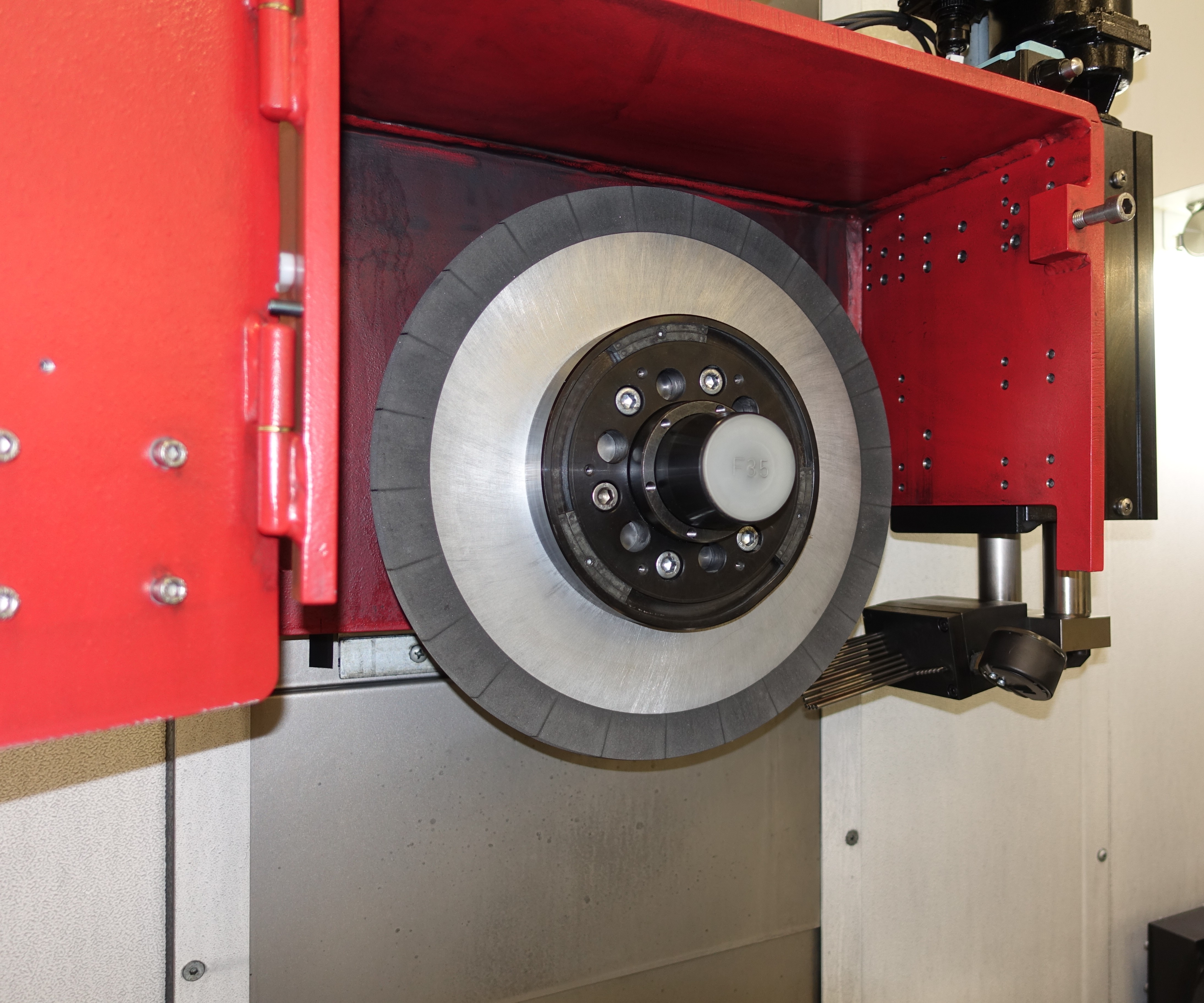
Superabrasive wheels such as the Norton Winter Paradigm wheel seen here permit creep-feed grinding without a demand for continuous dressing. The unit for intermittent dressing is seen on the machine’s table just within the frame of the photo.
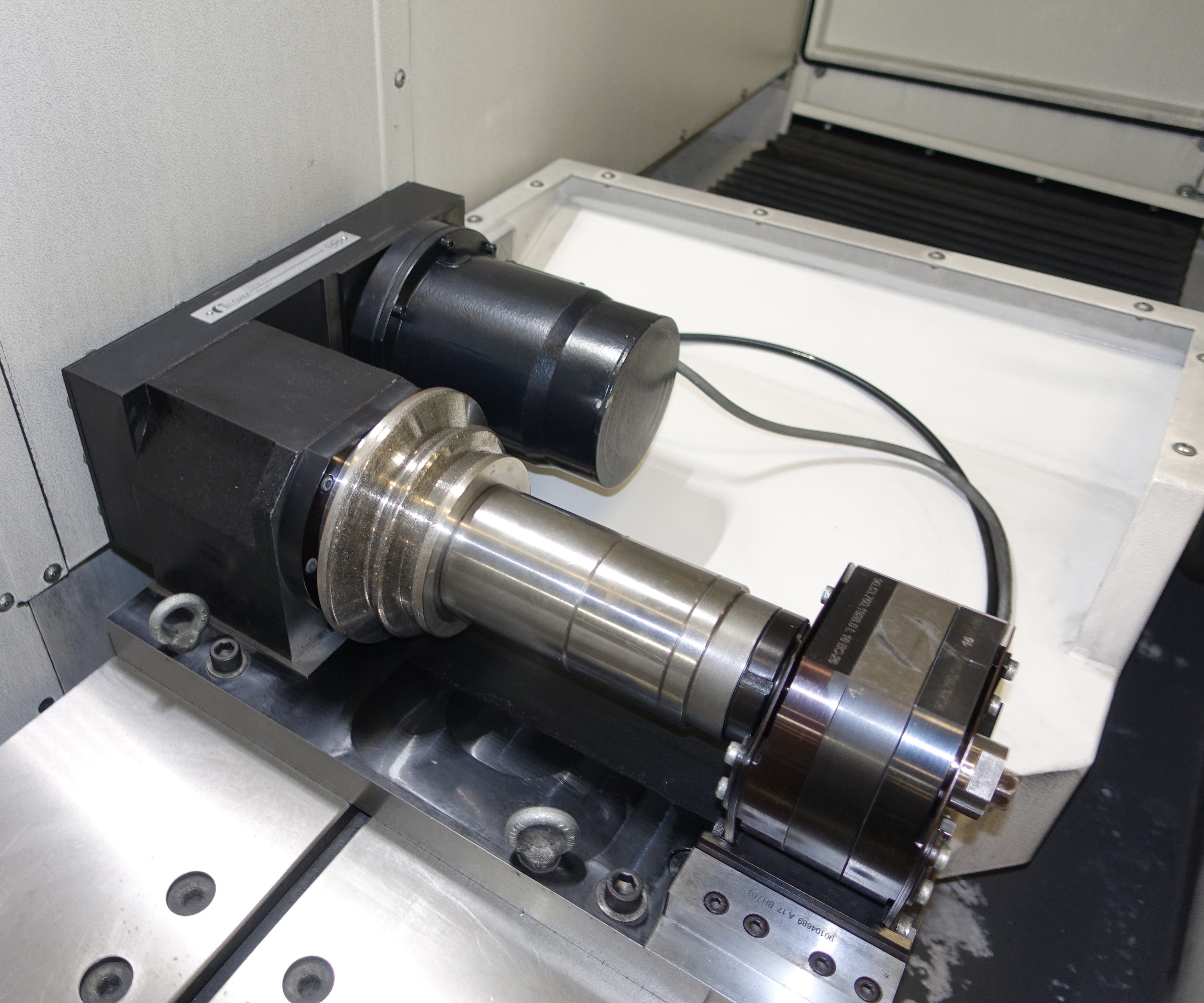
This is the intermittent dressing unit from the previous photo. A wheel allowing dressing with a unit such as this permits creep-feed grinding to be performed on older or less-expensive machines.
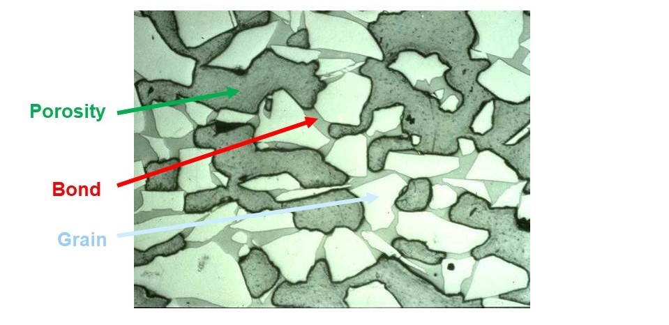
Wheel porosity is a useful feature for creep-feed grinding because it aids coolant infiltration. Metal-bond superabrasive wheels thrive in creep-feed grinding of ceramic-matrix materials because of their high porosity.
In machining superalloys used to make aircraft parts, creep-feed grinding can now deliver a metal-removal rate equivalent to milling. Rather than finishing the process, grinding increasingly now offers the chance to be the process.


Here is a creep-feed grinding setup employing many of the elements discussed in this article. Seen here are a profiled grinding wheel, continuous-dressing unit directly above it, nozzles following the profile of the wheel, and tooling (the white plastic piece) for capturing and pooling the coolant.
Is grinding the material-removal process of the future? Consider these two important, ongoing trends in machining:
- Tighter tolerances. Better-performing systems in automobiles and other end products are driving the demand for increasingly tighter feature tolerances and finer surfaces on machined parts.
- Harder materials. Manufacturers are increasingly using superalloys, ceramics and other materials engineered for high hardness at high temperatures. This results in parts that are more durable, but harder to machine.
And to these trends in machining in general, one can add an important material-engineering trend that directly affects grinding: Improved grains and bonds in grinding wheels are delivering more effective performance. Together, all these developments suggest there will be greater use of grinding in the future. They also point to an implication even more specific than that. Taken together, these factors suggest that we will see increasingly greater use of creep-feed grinding.


What is creep-feed grinding? Compared to the more common surface grinding, creep-feed grinding employs a heavier grinding depth combined with a slow traverse rate, generally with a profiled grinding wheel, to generate a given geometric form at a material removal rate (MRR) that is much higher than the finishing passes for which grinding is generally known.
The MRR is why creep-feed grinding offers such promise. In machining a hard, high-temperature alloy such as Inconel or an even harder material such as a ceramic-matrix composite, the potential MRR of a heavier metal cutting process such as milling is limited. Greater use of these hard materials therefore means greater challenges for milling. But developments such as grinding wheel improvements have enabled creep-feed grinding’s MRR in these same materials to significantly increase. According to grinding wheel manufacturer Saint-Gobain Abrasives, which is known by the brand Norton, we have already reached the point at which grinding is no longer a terminal process in the machining sequence for a part. Instead, in a significant and growing number of cases, grinding is the process.
I recently spoke about this shift with members of the Norton engineering team during a visit to the company’s Higgins Grinding Technology Center in Northborough, Massachusetts. This Boston-area facility, where application engineering and product testing are performed on grinding wheels and other products, is one of four such grinding technology centers for the company worldwide. On the day I visited, much of the testing I saw on CNC grinders on the facility’s R&D floor related to creep-feed grinding. Team members I met with included Technology Manager Robin Bright, PhD; Senior Application Engineer Bruce Gustafson; Director of Bonded Abrasives Brian Rutkiewicz; and High-Performance Materials Technologist Philip Varghese, PhD—all creep-feed experts who have been involved with a company initiative called “Machining-to-Grinding” aimed at helping support manufacturers making a transition from metal cutting to greater use of grinding. This initiative, which has focused on aerospace manufacturers as they shift to difficult-to-machine alloys and composites, has also realized success for gear makers and now is finding applications in automotive manufacturing.
I asked the team members what is important to understand about creep-feed grinding today. Their replies covered the following 10 points, the first of which explores the somewhat ambiguous question of just where creep-feed begins.
1. Creep-feed grinding has no formal definition.
“There are no creep-feed police,” Gustafson says. The principal defining characteristic of creep-feed grinding is a depth of cut that is high for grinding, but opinions differ on precisely what depth marks the transition. In his work involving aircraft-engine-related grinding applications, he has noted that engineers in this sector frequently mark the beginning of creep-feed at 0.015 inch. His own opinion places the transition earlier than this; he thinks a grinding depth of 0.005 inch can qualify as creep-feed. In either case, he says the choice is arbitrary, with no formal definition. Likely it is reasonable to think of your deep-grinding application as creep-feed, and you may have done grinding that was arguably creep-feed without realizing it.
2. Creep-feed is both a low-force and a high-force process.
Rutkiewicz characterizes the creep-feed process by pointing to this seemingly contradictory depiction: The force in the cut is low from one perspective and high from another. While each cutting particle on the grinding wheel experiences a low force relative to other modes of grinding, the force imparted to the machine and part overall is likely to be high.
Compensating for the heavy depth of cut in creep-feed is a traverse rate (feed rate) that is low, often on the order of 5 to 20 inches per minute. The low feed rate and corresponding chip load mean the cutting force upon every individual grit of the surface of the grinding wheel is also low. Wheel life and power efficiency both potentially benefit from this.
And yet, a lot of grits are engaged. The larger depth of cut of creep-feed means a longer arc of the wheel is submerged in the part, increasing force overall. As a result, the requirements of a grinding machine used in this process include spindle power of at least 15 to 20 horsepower per inch of grinding wheel width and a static loop stiffness of 100,000 pounds per inch for each inch of grinding wheel width.
3. Creep-feed offers advantages over conventional grinding.
Compared to a conventional process that makes faster, lighter passes, creep-feed grinding offers the following benefits:
- Shorter cycle time. True, the feed rate is low, but the increased depth of cut more than compensates for this. Additionally, the reduced total number of passes means there is less time lost to acceleration and deceleration as the machine reverses.
- Reduced machine wear, another beneficial result of the reduced frequency of machine reversals.
- Longer wheel life. The reduced force per grit (point 2 above) means that this high-MRR process is actually less demanding on the wheel.
- Finer-tolerance and more complex geometric for The low feed rate and low force per grit enable superior control over the outcome of the grinding operation.
All these benefits come with one very large downside to creep-feed grinding, discussed in the next point.
4. Coolant is crucial.
The long arc of wheel engagement translates to greater heat generation in the process. Coolant is therefore crucial to using creep-feed grinding effectively. Other machining processes routinely apply flood coolant by using a nozzle to point the coolant stream in roughly the direction of the cut, but creep-feed requires coolant application to be taken more seriously. Various considerations are employed to ensure as much of the coolant’s heat-transfer capacity is realized as possible, including:
- Coolant delivery speed is matched to the speed at the wheel surface. Syncing coolant-flow speed with the speed at which any point of the wheel is passing ensures more of the coolant meets and follows with the wheel.
- Coolant-delivery nozzles are arranged in profiles that match the profile of the grinding wheel. (See photo in the slideshow above.)
- Special coolant-collection tooling is used in creep-feed grinding. A ramp on the exit side of the part collects coolant and enables it to pool at the wheel for still greater wheel exposure to the fluid. This ramp might even be machined to match the part profile.
5. Down grinding is preferred for MRR.
Similar to milling in which the two possible directions of tool rotation relative to the workpiece produce either conventional milling or climb milling, the two possible directions of grinding wheel rotation produce either “up” grinding or “down” grinding. Dr. Bright says creep-feed’s preference is down grinding when the objective is high MRR. The rotation of the wheel in down grinding causes the bottom of the wheel to move in the same direction as the feed of the part. This type of grinding causes any point of the wheel—any grit of the wheel—to first meet the workpiece where the material engagement is greatest. (See diagram in the slideshow above.)
Again, heat is the reason for this preference where stock removal is high. To grind in the other direction is to have the grit first meet the material without cutting into it. “The result is that each grit is not making a chip right away,” Dr. Bright says. “Initially, the grits are sliding and plowing, which causes friction and excess heat into the part.” Down grinding, though it might seem more abrupt, allows for a cooler grinding process, as grits are forming chips when they first engage the part. By contrast, up grinding is preferred where the objective is either a fine surface finish or extending the life of the abrasive.
6. Intermittent dressing is becoming more acceptable.
Because the material removal per pass is so great in creep-feed grinding, aluminum-oxide wheels used in this process tend to require continuous dressing. A dressing wheel applied to the grinding wheel as it is grinding keeps the wheel sharp at all times. Indeed, continuous-dress capability is potentially another machine requirement for creep-feed grinding, in addition to power and stiffness.
However, newer grinding wheels with ceramic grit make it possible to avoid this need. Because the ceramic wheels remain sharp for a longer period of time, they make it possible to use intermittent dressing, meaning dressing using a separate wheel located elsewhere in the workzone apart from the grinding head. Dressing only when needed allows the wheel to last longer, and by eliminating the need for continuous-dress capability, the more advanced grinding wheel makes it possible to perform creep-feed grinding on a less expensive machine.
7. Superabrasive wheels can move beyond tool grinding.
A third wheel type is also likely suitable for intermittent dressing. Dressable metal-bond superabrasive wheels using diamond or cubic boron nitride (CBN) grit have been used in cutting tool manufacturing for grinding composite, cermet and ceramic tools. Based on the similarity of material properties, Norton engineers believe these wheels could also efficiently grind ceramic-matrix composite and gamma titanium aluminide parts for aerospace. Another useful feature of these wheels is their porosity. For grinding wheels in general that are engineered for creep-feed grinding, material grains are spaced widely to create microscopic porosity allowing coolant to infiltrate the wheel. In a superabrasive wheel such as the Norton Winter Paradigm product line, the metal bond allows for a wheel porosity ranging to 46 percent.
In some cases, superabrasive wheels also can be used without any dressing. Single-layer metal-bond superabrasive wheels designed for no dressing have been applied to realize creep-feed grinding on CNC milling machines.
8. Broaching now has a low-footprint rival.
Milling is not the only competitor to creep-feed grinding. Another is broaching, specifically the broaching that is applied to realize the fir-tree forms in aircraft-engine disks made of superalloy. A form such as this can be generated through creep-feed grinding. The result might be considerable floor-space savings. Because of the long linear travel it requires, the broaching machine for this operation could easily be 30 to 40 feet long. Creep-feed grinding offers the chance to perform the same machining within a standard-size machine tool.
9. In aerospace, the MRR can match that of milling.
Dr. Varghese stresses again: The view that grinding is a finishing process and the final touch applied to a machined part to realize dimensional and surface tolerances—that is, the historical role of grinding—is a view that will become less and less inclusive of all that grinding can do as advanced workpiece materials are used more widely. In the past, 1 cubic inch per minute per inch of wheel width is the typical specific MRR that has been expected of grinding. In superalloy grinding applications today on CNC machines using engineered wheels, creep-feed grinding can realize a specific MRR of 18 cubic inches per minute per inch of wheel width—resulting in overall MRR equal to or better than what a milling cutter might do in that same workpiece material, he says.
Another important area of advance has been in the energy demand creep-feed grinding requires. From the perspective of the machine, creep-feed is a high-force process (point 2), but the sharper-cutting grit in modern wheels reduces that force. Improved wheel porosity for conveying swarf and coolant along with improved coolant techniques also help to improve energy efficiency. As a result, the specific energy of creep-feed grinding—the energy required to remove each cubic inch of material—has become comparable to milling as well.
10. Creep-feed offers the promise to relocate heat treatment.
But comparing milling to grinding in terms of their machining cycles alone might miss one of the greatest benefits of creep-feed: a fundamental change to the sequence of the process. In that traditional role of grinding as a finishing operation, the part often undergoes heat treatment just ahead of this step. Grinding is an effective process for machining in the harder, post-heat-treatment state, though milling the part in this state would be problematic. Thus, most of the part’s machining is carried out through milling while the workpiece is still soft, then comes heat treating, then the part may receive a final light milling step before grinding or it may go to grinding directly. This sequence—milling, sending the part away for heat treatment, bringing the part back to the shop for the operations including grinding—is second nature to manufacturers and a standard way many parts are made.
However, creep-feed grinding can undo that sequence. The workpiece could be heat treated first, meaning the workpiece could be brought to its final hardness first, before any machining is done. Creep-feed grinding would eliminate the interruption, delay and coordination necessary to ship a partially completed part away for this off-site step. Matching the MRR of milling may be the benchmark enabling grinding to take on a larger role in production, but reordering the steps needed in production may in some cases be where creep-feed grinding realizes its greatest savings.


Related Content

Understanding Errors In Hand-Held Measuring Instruments
Different instruments (and different operators) are prone to different errors.
Read More
Selecting The Right Welder
Many machine shops, on occasion, have a need for welding. It may be for maintenance purposes, repair or to fill the odd contract. This story is a welding process primer for those shops whose main business isn't welding but need to know some basics.
Read More
10 Tips for Titanium
Simple process considerations can increase your productivity in milling titanium alloys.
Read More
How To Calibrate Your Calipers
If you’re interested in calibrating your own digital, dial or Vernier calipers, here are some steps to take to make sure it goes off without a hitch.
Read MoreRead Next


3 Mistakes That Cause CNC Programs to Fail
Despite enhancements to manufacturing technology, there are still issues today that can cause programs to fail. These failures can cause lost time, scrapped parts, damaged machines and even injured operators.
Read More
The Cut Scene: The Finer Details of Large-Format Machining
Small details and features can have an outsized impact on large parts, such as Barbco’s collapsible utility drill head.
Read More