
Key CNC Concept No. 1—The Fundamentals Of Computer Numerical Control
Though the thrust of this presentation is to teach you CNC usage, it helps to understand why these sophisticated machines are so important. Here are but a few of the more important benefits offered by CNC equipment.
.jpg;width=70;height=70;mode=crop;format=webp)
Share


This is the first article in a 10-part series about the Key Concepts of Computer Numerical Control. For an introduction to the approach of this series read this article.
What are the benefits of computer numerical control?
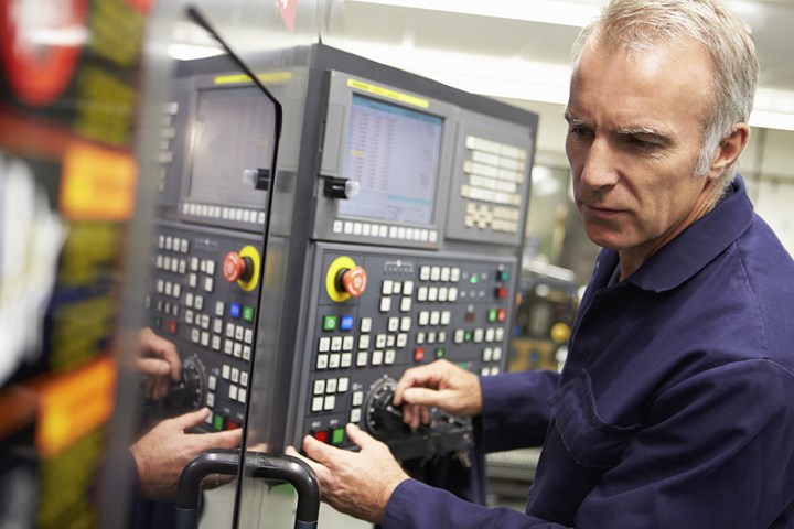
The first benefit offered by all forms of CNC machine tools is improved automation. The operator intervention related to producing workpieces can be reduced or eliminated. Many CNC machines can run unattended during their entire machining cycle, freeing the operator to do other tasks. This gives the CNC user several side benefits including reduced operator fatigue, fewer mistakes caused by human error, and consistent and predictable machining time for each workpiece. Since the machine will be running under program control, the skill level required of the CNC operator (related to basic machining practice) is also reduced as compared to a machinist producing workpieces with conventional machine tools.


The second major benefit of CNC technology is consistent and accurate workpieces. Today's CNC machines boast almost unbelievable accuracy and repeatability specifications. This means that once a program is verified, two, ten, or one thousand identical workpieces can be easily produced with precision and consistency.
A third benefit offered by most forms of CNC machine tools is flexibility. Since these machines are run from programs, running a different workpiece is almost as easy as loading a different program. Once a program has been verified and executed for one production run, it can be easily recalled the next time the workpiece is to be run. This leads to yet another benefit, fast change-overs.
Since these machines are very easy to set up and run, and since programs can be easily loaded, they allow very short setup time. This is imperative with today's just-in-time production requirements.
Motion Control—The Heart Of CNC
The most basic function of any CNC machine is automatic, precise, and consistent motion control. All forms of CNC equipment have two or more directions of motion, called axes. These axes can be precisely and automatically positioned along their lengths of travel. The two most common axis types are linear (driven along a straight path) and rotary (driven along a circular path).
Instead of causing motion by manually turning cranks and handwheels as is required on conventional machine tools, CNC machines allow motions to be actuated by servomotors under control of the CNC, and guided by the part program. Generally speaking, the motion type (rapid, linear, and circular), the axes to move, the amount of motion and the motion rate (feed rate) are programmable with almost all CNC machine tools.
A CNC command executed within the control (commonly through a program) tells the drive motor to rotate a precise number of times. The rotation of the drive motor in turn rotates the ballscrew. And the ballscrew drives the linear axis. A feedback device at the opposite end of the ballscrew allows the control to confirm that the commanded number of rotations has taken place.
Though a rather crude analogy, the same basic linear motion can be found on a common table vise. As you rotate the vise crank, you rotate a leadscrew that, in turn, drives the movable jaw on the vise. By comparison, a linear axis on a CNC machine tool is extremely precise. The number of revolutions of the axis drive motor precisely controls the amount of linear motion along the axis.
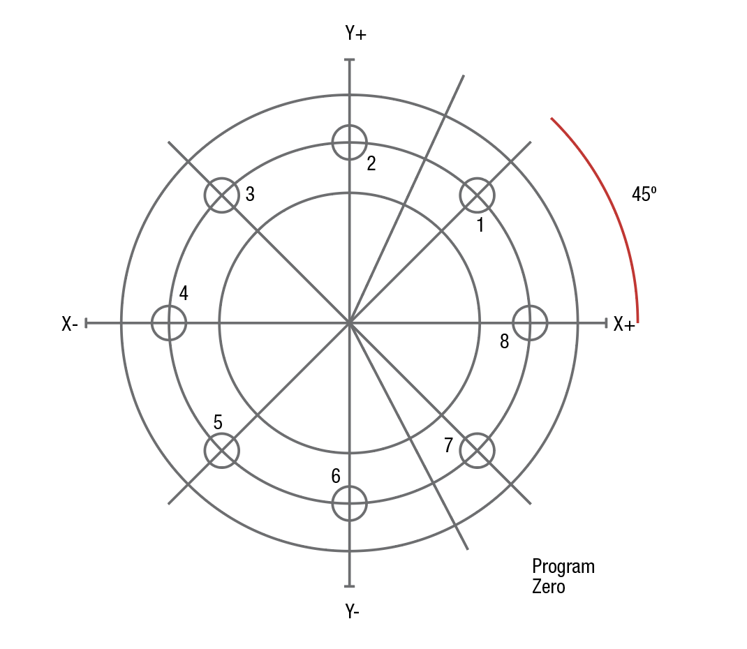
Figure 1: In this example, program zero is placed in the center of the ring. Notice that any coordinates to the left of, or below, program zero are specified as negative positions.
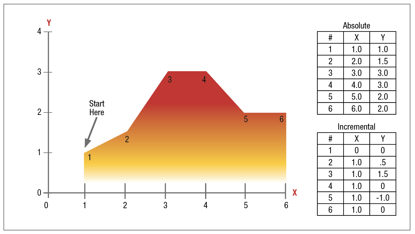
Figure 2: It is very easy to tell the precise location of the tool in any command given in the absolute mode. In the incremental mode, it can be very difficult to determine the tool's current position for a given motion command.
How Axis Motion Is Commanded—Understanding Coordinate Systems
It would be unfeasible for the CNC user to cause axis motion by trying to tell each axis drive motor how many times to rotate in order to command a given linear motion amount. (This would be like having to figure out how many turns of the handle on a table vise will cause the movable jaw to move exactly one inch!) Instead, all CNC controls allow axis motion to be commanded in a much simpler and more logical way by utilizing some form of coordinate system. The two most popular systems used with CNC machines are the rectangular—or "cartesian"—coordinate system and the polar coordinate system. By far, the most common is the rectangular coordinate system.
One very common application for the rectangular coordinate system is graphing.
Let's take what we now know about graphs and relate it to CNC axis motion. Instead of plotting theoretical points to represent conceptual ideas, the CNC programmer is going to be plotting physical endpoints for axis motions. Axes are broken into increments. But instead of being broken into increments of conceptual ideas like time and productivity, each linear axis of a CNC machine's rectangular coordinate system is broken into increments of measurement. In the inch mode, the smallest increment may be 0.0001 inch. In the metric mode, the smallest increment may be 0.001 millimeter. (By the way, for rotary axis the increment is 0.001
degrees.)
Each axis within the CNC machine's coordinate system must start somewhere. For CNC purposes, this origin point is commonly called the program zero point (also called work zero, part zero, or program origin). Typically, the program zero point is chosen as the point where all dimensions begin.
With this technique, if the programmer wishes the tool to be sent to a position one inch to the right of the program zero point, X1.0 is commanded. If the programmer wishes the tool to move to a position one inch above the program zero point, Y1.0 is commanded. The control will automatically determine how many times to rotate each axis drive motor and ballscrew to make the axis reach the commanded destination point. This lets the programmer command axis motion in a very logical manner.
With the examples given so far, all points happened to be up and to the right of the program zero point. This area up and to the right of the program zero point is called a quadrant (in this case, quadrant number one). It is not uncommon on CNC machines that endpoints needed within the program fall in other quadrants. When this happens, at least one of the coordinates must be specified as minus. Figure 1 shows one common application of when endpoints fall in all four quadrants and negative coordinates must be specified.
Absolute Versus Incremental Motion
All discussions to this point assume that the absolute mode of programming is used. In the absolute mode, the endpoints for all motions will be specified from the program zero point. For beginners, this is usually the best and easiest method of specifying endpoints for motion commands. However, there is another way of specifying endpoints for axis motion.
In the incremental mode, endpoints for motions are specified from the tool's current position, not from program zero. With this method of commanding motion, the programmer must always be asking, "How far should I move the tool?" While there are times when the incremental mode can be very helpful, generally speaking, this is the more cumbersome and difficult method.
Be careful when making motion commands. Beginners have the tendency to think incrementally. If working in the absolute mode (as beginners should), the programmer should always be asking "To what position should the tool be moved?" This position is relative to program zero, not from the tool's current position. Figure 2 shows two identical series of movements, one in the incremental mode and the other in the absolute mode.
Aside from making it very easy to determine the current position for any command, another benefit of working in the absolute mode has to do with mistakes made during motion commands. In the absolute mode, if a motion mistake is made in one command of the program, only one movement will be incorrect. On the other hand, if a mistake is made during incremental movements, all motions from the point of the mistake will also be incorrect.
Assigning Program Zero
Keep in mind that the CNC control must be told the location of the program zero point by one means or another. How this is done varies dramatically from one CNC machine and control to another. An older method is to assign program zero in the program. With this method, the programmer tells the control how far it is from the program zero point to the starting position of the machine. This is commonly done with a G92 (or G50) command at least at the beginning of the program and possibly at the beginning of each tool.
A generally better way to assign program zero is through some form of offset. Machining center control manufacturers commonly call offsets used to assign program zero fixture offsets. Turning center manufacturers commonly call offsets used to assign program zero for each tool geometry offsets. More on how program zero can be assigned will be presented during key concept number four.
Other Points About Axis Motion
To this point, our primary concern has been to show you how to determine the endpoint of each motion command. As you have seen, doing this requires an understanding of the rectangular coordinate system. However, there are other concerns about how a motion will take place. For example, the type of motion (rapid, straight line, circular, etc.), and motion rate (feed rate) will also be of concern to the programmer. We'll discuss these other considerations during key concept number three.
The CNC Program
Almost all current CNC controls use a word address format for programming. (The only exceptions to this are certain conversational controls.) By word address format, we mean that the CNC program is made up of sentence-like commands. Each command is made up of CNC words, each of which has a letter address and a numerical value. The letter address (X, Y, Z, etc.) tells the control the kind of word and the numerical value tells the control the value of the word. Used like words and sentences in the English language, words in a CNC command tell the CNC machine what it is we wish to do at the present time.
Each word has a letter address and a numerical value. The letter address tells the control the word type. CNC control manufacturers do vary with regard to how they determine word names (letter addresses) and their meanings. The beginning CNC programmer must reference the control manufacturer's programming manual to determine the word names and meanings. Here is a brief list of some of the word types and their common letter address specifications.
O - Program number (Used for program identification)
N - Sequence number (Used for line identification)
G - Preparatory function (See below)
X - X-axis designation
Y - Y-axis designation
Z - Z-axis designation
R - Radius designation
F - Feedrate designation
S - Spindle speed designation
H - Tool length offset designation
D - Tool radius offset designation
T - Tool Designation
M - Miscellaneous function
As you can see, many of the letter addresses are chosen in a logical manner (T for tool, S for spindle, F for feed rate, etc.). A few require memorizing.
There are two letter addresses (G and M) that allow special functions to be designated. The preparatory function (G) specifies is commonly used to set modes. We already introduced absolute mode, which is specified by G90 and incremental mode, specified by G91. These are but two of the preparatory functions used. You must reference your control manufacturer's manual to find the list of functions for your machine.
Like preparatory functions, miscellaneous functions (M words) allow a variety of special functions. Miscellaneous functions are typically used as programmable switches (like spindle on/off, coolant on/off, and so on). They are also used to allow programming of many other programmable functions of the CNC machine tool.
To a beginner, all of this may seem like CNC programming requires a great deal of memorization. But rest assured that there are only about 30-40 different words used with CNC programming. If you can think of learning CNC manual programming as like learning a foreign language that has only 40 words, it shouldn't seem too difficult.
Decimal point programming
Certain letter addresses (CNC words) allow the specification of real numbers (numbers that require portions of a whole number). Examples include X-axis designator (X), Y-axis designator (Y), and radius designator (R). Almost all current model CNC controls allow a decimal point to be used within the specification of each letter address. For example, X3.0625 can be used to specify a position along the X-axis.
On the other hand, some letter addresses are used to specify integer numbers. Examples include the spindle speed designator (S), the tool station designator (T), sequence numbers (N), preparatory functions (G), and miscellaneous functions (M). For these word types, most controls do not allow a decimal point to be used. The beginning programmer must reference the CNC control manufacturer's programming manual to find out which words allow the use of a decimal point.
Other programmable functions
All but the very simplest CNC machines have programmable functions other than just axis motion. With today's full-blown CNC equipment, almost everything about the machine is programmable. CNC machining centers, for example, allow the spindle speed and direction, coolant, tool changing, and many other functions of the machine to be programmed. In similar fashion, CNC turning centers allow spindle speed and direction, coolant, turret index, and tailstock to be programmed. And all forms of CNC equipment will have their own set of programmable functions. Additionally, certain accessories like probing systems, tool length measuring systems, pallet changers, and adaptive control systems may also be available and will require programming considerations.
The list of programmable functions will vary dramatically from one machine to the next, and the user must learn these programmable functions for each CNC machine to be used. In key concept number two, we will take a closer look at what is typically programmable on different forms of CNC machine tools.
Learn more about key concepts of computer numerical control:
Key CNC Concept #2—Know Your Machine
Key CNC Concept #3—Understanding CNC Motion Types
Key CNC Concept #4—The Forms Of Compensation
Key CNC Concept #5—The Importance Of Program Formatting
Key CNC Concept #6—Methods For CNC Programming
Key CNC Concept #7—Know The Machine From An Operator's Viewpoint
Key CNC Concept #8—The Modes Of Machine Operation
Key CNC Concept #9—The Key Sequences Of Operation


Related Content

4 Tips for Staying Profitable in the Face of Change
After more than 40 years in business, this shop has learned how to adapt to stay profitable.
Read More
Understanding Process Damping in Milling Operations
Despite the advances in modeling machining operations over the past decades, process damping remains a topic of interest, including new tool designs that increase the effect.
Read More
4 Manufacturing Trends That Cannot Be Ignored
The next five years will present their own unique set of challenges, and shops can alleviate them by embracing these technologies and trends.
Read More
How to Mitigate Risk in Your Manufacturing Process or Design
Use a Failure Mode and Effect Analysis (FMEA) form as a proactive way to evaluate a manufacturing process or design.
Read MoreRead Next

OEM Tour Video: Lean Manufacturing for Measurement and Metrology
How can a facility that requires manual work for some long-standing parts be made more efficient? Join us as we look inside The L. S. Starrett Company’s headquarters in Athol, Massachusetts, and see how this long-established OEM is updating its processes.
Read More