
Machining 101: What are Machining Centers?
Machining centers offer a wide range of possible operations, but that adaptability comes with the need to stay flexible and perform successful measurements at all times.


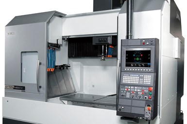
Most machining centers on the market feature numerical control (CNC) and serve more than one purpose. Many can perform combinations of operations such as milling, drilling, boring, tapping and reaming in a single setup. Machining centers come in three general types: horizontal three-axis, vertical three-axis and five-axis machines (four- and six-axis machines exist, but are less common). Horizontal and vertical three-axis machines differ primarily in the inclination of the spindle, with the spindles of horizontal machines parallel to the surface of the machine table and the spindles of vertical machines perpendicular to the surface, although individual constructions vary widely to support different applications.
Three-axis machines move on three CNC-controllable planes. For a vertical machining center, the X-axis controls left-and-right movement, parallel to the workholding surface; the Y-axis controls front-and-back movement, perpendicular to the X- and Z-axes; and the Z-axis controls up-and-down movement. Most machines use a fixed spindle and a moving table, or a fixed table and a moving spindle. Spindle rotation is never considered an axis.


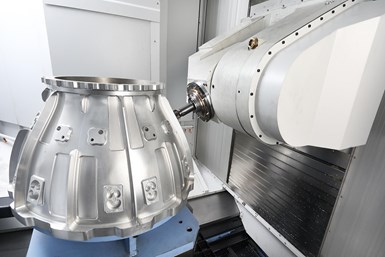
Five-axis (and four-axis and six-axis) machines introduce additional axes that enable the table or spindle head to rotate and pivot. The A-axis involves X-axis rotation, while the B-axis is paired to the Y-axis and the C-axis is paired to the Z-axis.
Spindle Adaptation
Rotating cutting tools like face mills, end mills and slotting mills require a high degree of mounting accuracy and rigidity to achieve optimal tool life and productivity. These tools can be directly mounted to the spindle face or be mounted through an intermediate tapered-shank adapter, commonly referred to as a toolholder. Examples of these adapters include end mill adapters, shell mill adapters, stub arbors and collet chucks.
Most adapter systems use a tapered shank held in the machine spindle by either a threaded drawbar or a drawbar that grips a retention knob at the back of the adapter. The adapters are usually driven by keys mounted on the spindle face. Adapter size typically indicates machine rigidity, with larger adapters signifying higher connection rigidity. Retention knobs tend to be unique to each machine tool manufacturer and spindle size, so users must take care that the correct knob is in use.
The standard taper has a ratio of 7:24 (translating to 3.500 inches per foot, 291.663 mm per meter; or 8 degrees, 17 minutes and 50 seconds). Different names for this taper include the steep, American Standard or ISO taper. The 7:24 ratio makes an angle sufficiently large for self-releasing features, and while several national standards have evolved to mate adapters to spindles, all try to be compatible with this taper. The steep taper only requires the taper itself to meet high accuracy requirements when machining, making parts that use it relatively simple and inexpensive to manufacture.
Steep-taper adapters are held deep within the spindle to reduce tool overhang from the spindle’s face. These tapered holders are relatively easy to remove because they do not lock into place or become jammed in the spindle. However, the tapered surface must also locate the adapter relative to the spindle and clamp it rigidly into place. Due to the expense of the high machining accuracy required to ensure continuous face and taper contact, these adapters can face problems with unbalance and radial location at high revolutions.
Other common taper systems include the Brown and Sharpe, Morse, and Jarno tapers. These and the steep taper are commonly called the “self-holding” tapers because they have angles small enough to hold shanks in place by friction alone while ensuring tool rotation within the socket.
Adapter Systems
Adapters from the CAT V system, as well as its BT and DIN 69871 regional equivalents, mount directly into the spindle, with a drawbar grasping the retention knob at the back of the adapter. This system is characterized by the flange, which the machine’s tool-changing device uses to pick a tool from the tool changer or magazine for use in the proper tapered spindle hole. The rears of these adapters are threaded, so a single holder can use a variety of retention knobs to accommodate different machine grippers. BT and DIN 69871 are not interchangeable with CAT V, as the former two use metric sizing while the latter uses imperial sizing.
Unlike the CAT V system, National Machine Tool Builder Standard (NMTB) tapered-shank adapters require the machine drawbar to thread directly into the back of the adapter rather than to a retention knob. There is also no tool change groove, so these adapters are unsuitable for machine centers with automatic tool changers.
HSK (hollow shank kegel) system adapters are best for high-speed operations. The HSK shank is shorter and more compact than regular steep taper shanks. The HSK system also uses a hollow taper with a shallower ratio, at 1:10 (1.2 inches per foot; 100 mm per meter; or 2 degrees, 51 minutes and 53 seconds). HSK uses six different shank configurations, designated by the letters A-F. A-D specialize in relatively lower machine speeds, while E and F handle high-speed cutting. Most machine tool manufacturers offer machining centers with HSK spindles.
Hydraulic and shrink-fit adapters use hydraulic pressure and thermal contraction, respectively, to precisely center the cutting tool and minimize runout. Steep-taper and HSK versions of both can apply pressure evenly all the way around the tool surface to act as an accurate collet and automate the tool centering process.
Hydraulic toolholders have an expanding steel sleeve filled with oil. Turning the actuating screw in the toolholder increases the pressure on the fluid up to 15 tons per square inch. The walls of the sleeve bulge up to their elastic limits to clamp the tool shank, then relax to their original dimensions when pressure is relieved. Shrink-fit adapters have diameters slightly smaller than the diameters of the cutting tools they grip. Induction heating systems expand the adapter just enough for the tool shank to slip inside. As the gripping shaft cools, it grips the shank with up to 10,000 pounds of clamping force.
Some milling cutters mount directly to the spindle face, with the drive keys and threaded bolt-mounting hole on the spindle matching the keyslots and bolt-hole pattern on the cutter. After inserting a centering plug in the spindle taper, users can directly mount the cutter in what is called flat back mounting. As there is no extension or overhang from the spindle face with this method, it guarantees maximum rigidity.
Tool Balance
Standard adapters and tooling are normally satisfactory at spindle speeds up to 8,000 rpm. At faster speeds, specially balanced tooling can be critical for high tolerances and surface finishes.
Unbalance is a tool’s mass times its eccentricity (which is the distance from the tool’s center of rotation to its true center of mass). Eccentricity is measured in microns and tool mass in kilograms, so unbalance is measured in gram-millimeters. ISO 16084 is the standard for setting targets for tool and toolholder balance.
To evaluate unbalance in processes, users can perform trial runs one at a time with tools balanced to a variety of different values. Such an evaluation might start at an unbalance of 10 g-mm, then progress through a series of increasingly balanced tools until it achieves proper tolerances or accuracy and surface finish fail to improve any further.
Accuracy and Repeatability in Machining Centers
Although accuracy and repeatability are both vital, these specifications can be especially difficult to determine because different manufacturers use different definitions. In general, there are three standards for accuracy: unidirectional forward, unidirectional reverse and bidirectional (which is the average of the two). Repeatability — which is the distance between accuracy samples, tested over the full range of data points — generally has four standards: forward repeatability, reverse repeatability, bidirectional repeatability and scatter. “Lost motion,” also called “mean reversal error,” is the difference from center found when comparing marks made with forward and backward repeatability. Data collection typically repeats processes seven times, then creates a bell curve of results, calculating both the standard deviations and the mean. Different measurement standards use the standard deviations in different ways.
Different manufacturers also use different standards for accuracy and repeatability. Most standards output total values, though many builders advertise using smaller ± values. Even just considering the standards themselves, comparisons between them are of little use due to differences in calculations outputting different results. Six common standards are NMBTA (used primarily in the US, and the only standard to statistically calculate using bidirectional data), ISO 230-3-1988 (used in Europe), BSI BS 4656 Part 16 (used in Great Britain), VDI/GDQ 3441 (used in Germany), JIS B 6336-1986 (used in Japan) and ASME B5.54-92 (another U.S. standard).
Tool Measurement and Setting
Measuring a cutter’s length, diameter and profile can reduce variability and optimize machining processes. Traditionally, tool setting is performed offline with a tool setting gage that verifies the tool’s dimensions manually or through a bar code. This process is reliable for determining the workpiece tool offset, but does not translate how the toolholder, drawbar and spindle will align from tool to tool. Thus, perfect repeatability between cutting tool and spindle is rare.
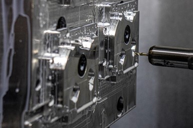
Laser measurement systems can perform dynamic measurement of tools as the spindle turns. Typically one-size-fits-all, noncontact laser beams present little risk of contamination, use less than one Watt and do not require special eye protection. The high-precision photoelectric beam is activated when broken, with the output traveling to the machine’s CNC or PLC, and onboard software comparing and coordinating the point of beam contact with known values in the control’s tool data tables. The measurement routine itself is an automatic macro built into the measurement software. Laser systems are compatible with diameters as small as 0.012 inch (0.3 mm), with accuracy to within a few microns.
Rotary and Linear Encoders
Machine tools use linear and rotary encoders to measure their own movements and stay on target. There are three types of encoder contacts — photoelectric (also called optical), magnetic and mechanical — but photoelectric encoder contacts are the most common.
Rotary encoders measure rotational movement drives, but spindles and recirculating ballscrews can also enable them to measure linear movements. Rotary encoders can be incremental or absolute.
Incremental rotary encoders have output signals that are evaluated by electronic counters that measure “increments.” For general length measurement applications — particularly the measure of slide movements using a recirculating ballscrew as the scale — shaft encoders that incorporate digitizing electronics are standard.
Absolute rotary encoders derive angular positional value from the pattern of a coded disc that provides values immediately after power switches on. The Gray coder and coders which use natural binary are most common, with many modern computer programs using the binary system to support high speeds.
Linear encoders can achieve results in the submicron range, which is especially useful for the semiconductor industry and ultra-precision machinery. These encoders transmit displacement information directly to a digital readout, NC controller or peripheral, and favor the photoelectric system.
Linear scales can be either enclosed or exposed. Enclosed linear scales have a scanning unit that is mounted on a small carriage guided by ball bearings along a glass scale. Sealing lips protect the scale from contamination. They are typically used for machine tools and cutting type machines, as well as machines in harsh environments.
Exposed linear scales also have a glass scale and scanning unit, but the two components are physically separated. With no contact or friction between the scanning unit and the scale, mounting is easier and traverse speed is faster. Applications include coordinate measuring machines, translation stages and material handling equipment.
Some variants of linear encoders use metal scales instead of glass, with maximum lengths up to 30 meters instead of glass scales’ three. Of particular note are encoders that utilize the interferential scanning principle, which makes use of unique diffractions of light waves. This system sees very high resolution and accuracy with a wide tolerance for the gap between scanner and scale, and displays excellent repeatability. It is better suited to thermal expansion of steel workpieces than a laser setup at short distances of less than or equal to one meter.
For recent topics in machine centers, visit the MMS Machining Centers information zone.


Related Content

When Organic Growth in Your Machine Shop Isn’t Enough
Princeton Tool wanted to expand its portfolio, increase its West Coast presence, and become a stronger overall supplier. To accomplish all three goals at once, acquiring another machine shop became its best option.
Read More
Threading On A Lathe
The right choices in tooling and technique can optimize the thread turning process.
Read More
Choosing Your Carbide Grade: A Guide
Without an international standard for designating carbide grades or application ranges, users must rely on relative judgments and background knowledge for success.
Read More
Watchmaking: A Machinist’s View
Old-world craftsmanship combines with precision machining on a vertical machining center and Swiss-type lathe to produce some of the only U.S.-made mechanical wristwatch movements.
Read MoreRead Next

The Cut Scene: The Finer Details of Large-Format Machining
Small details and features can have an outsized impact on large parts, such as Barbco’s collapsible utility drill head.
Read More
3 Mistakes That Cause CNC Programs to Fail
Despite enhancements to manufacturing technology, there are still issues today that can cause programs to fail. These failures can cause lost time, scrapped parts, damaged machines and even injured operators.
Read More
Obscure CNC Features That Can Help (or Hurt) You
You cannot begin to take advantage of an available feature if you do not know it exists. Conversely, you will not know how to avoid CNC features that may be detrimental to your process.
Read More