
Machining 101: What is Turning?
Turning uses a lathe to remove material from the outside of a rotating workpiece, while boring does the same from the inside of a rotating workpiece.

Share


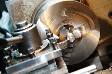
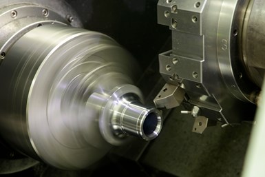
Turning is the process of using lathes to remove material from the outer diameter of a rotating workpiece. Single-point tools shear metal from the workpiece in (ideally) short, distinct, easily recyclable chips.
CNC lathes with constant surface speed control enable the operator to choose a surface speed, then the machine automatically adjusts the rpm as the cutting tool transverses the different diameters along the outer profile of the workpiece. Modern lathes also ship in single-turret and two-turret configurations, with single-turret machines having a horizontal and vertical axis and double-turret machines having one horizontal and vertical axis pair for each turret.


Early turning tools were solid, rectangular pieces of high-speed steel with rake and clearance angles on one end. When the tool dulled, machinists would sharpen it on a pedestal grinder for reuse. High-speed steel tools are still common on older turning machines, but carbide has become more popular, especially in brazed single-point form. Carbide sports better wear resistance and hardness, leading to better productivity and tool life, but it is more expensive and requires expertise to resharpen.
Speeds and Feeds
Turning is a combination of linear (tool) and rotational (workpiece) movement. Thus, cutting speed is defined as the rotational distance (recorded as sfm — surface feet per minute — or smm — square meters per minute — traveled in one minute by a point on the part surface). Feed rate (recorded in inches or millimeters per revolution) is the linear distance that the tool travels along or across a workpiece surface. Feed is also sometimes expressed as the linear distance the tool travels in a single minute (in./min or mm/min).
Feed rate requirements vary depending on the operation’s purpose. In roughing, for example, high feeds are generally better for maximizing metal removal rates, but require high part rigidity and machine power. Finish turning, meanwhile, might slow down the feed rate to produce the surface finish specified on the part blueprint.
Basics of Tool Geometry
Cutting tools’ effectiveness depends largely on the tool’s angle in relation to the workpiece. The terms defined in this section reference inserts to define cutting and relief angles, but can also apply to brazed single-point tools.
Top rake angle (also called back rake angle) is the angle formed between the angle of inclination of the insert and the line perpendicular to the workpiece when viewing the tool from the side, front to back. Top rake is positive when it slopes downward from the cutting point and into the shank, neutral when the line from the top of the insert is parallel with the top of the shank, and negative when it slopes upward from the cutting point and above the shank. Inserts and toolholders are also categorized as positive or negative. Positive inserts have angled sides and mount into toolholders with positive top and side rake angles. Negative inserts have square sides relative to the top face of the insert and mount into toolholders with negative top and side rake angles. Top rake angle is unique in that it is dependent on the geometry of the insert — a positive ground or a molded chipbreaker can change the effective top rake angle from negative to positive. Top rake angles also tend to be greater with softer and more ductile workpiece materials, which require high positive shearing angles, while harder and tougher materials are best cut with neutral or negative geometries.
Side rake angles are formed between the face of the insert and the line perpendicular to the workpiece when viewing the end. These angles are positive when they slope away from the cutting edge, neutral when they are perpendicular to the cutting edge, and negative when they slope upward. The possible thickness of the tool depends on the side rake angle, with smaller angles allowing for thicker tools that increase strength but require higher cutting forces. Larger angles produce thinner chips and reduce cutting force requirements, but past a maximum recommended angle, the cutting edge weakens and heat transfer diminishes.
End cutting edge angles form between the insert cutting edge on the end of the tool and a line perpendicular to the back side of the tool shank. This angle determines the clearance between the cutting tool and the finished surface of the workpiece.
Located below the end cutting edge, the end relief angle forms between the end face of the insert and a line perpendicular to the base of the toolholder. Tip overhang can make the end clearance angle (which is formed by the end face of the toolholder and a line perpendicular to the base of the toolholder) larger than the relief angle.
Side relief angle describes the angle below the side cutting edge. It is formed by the side face of the insert and a line perpendicular to the base of the toolholder. As with the end relief angle, tip overhang can make the side clearance angle (formed by the side face of the toolholder and a line perpendicular to the base of the toolholder) greater than the relief angle.
The lead angle (also called the side cutting edge angle or the attack angle) forms between the insert side cutting edge and the side of the tool shank. The angle leads the tool into the workpiece, and enlarging it produces wider, thinner chips. The geometry of the workpiece and the material condition are primary considerations when selecting the lead angle for a cutting tool. For example, tools with emphasized lead angles enable respectable productivity rates when cutting through scale, interruptions or hardened surfaces, without subjecting the cutting tool edge to severe shock. Operators must balance this benefit against increased part deflection and vibration, as larger lead angles create higher radial forces. Zero-degree lead angle turning tools produce chips equal in width to the turning operation’s cutting depth, while lead angle cutting tools make the effective cutting depth and corresponding chip width exceed the actual cutting depth on the workpiece. Most turning operations are efficiently performed within a lead angle range of 10 to 30 degrees (metric systems invert the angle from 90 degrees, making the ideal lead angle range 80 to 60 degrees).
Sufficient relief and clearance angles are both necessary on the end and the side for the tool to enter the cut. Without clearance, chip formation cannot occur, but without adequate relief, the cutter will rub and produce heat. Single-point turning tools also require end and side clearance angles to enter the cut.
Turning subjects workpieces to tangential, radial and axial cutting forces. Tangential force has the greatest effect on power consumption; axial (feed) force exerts pressure through the part in a longitudinal direction; and radial (depth of cut) force tends to push the workpiece and toolbar apart. “Cutting force” is the sum of all three of these forces. With a zero-degree lead angle, they have a ratio of 4:2:1 (tangential : axial : radial). As the lead angle increases, the axial force shrinks and the radial cutting force grows.
Toolholder style, nose radius and insert shape also have profound impacts on the potential maximum effective cutting edge length of turning inserts. Certain insert radius and toolholder combinations may require dimensional compensation to make full use of this cutting edge.
Nose Radius and Surface Finish
Surface finish in a turning operation depends on the rigidity of the tool, machine and workpiece. Once rigidity is assured, the relationship between the machine feed (in./rev or mm./rev) and the nose contour of the insert or cutting tool can be used to determine the workpiece’s surface finish. The nose contour is expressed as a radius — up to a certain point, a larger radius translates to better surface finish, but too large of a radius can introduce chatter. For machining operations where a smaller-than-optimum radius is required, feed rate may need to be reduced for the desired finish.
Productivity
After achieving the appropriate level of power, productivity improves alongside increases to depth of cut, feed rate and speed.
Depth of cut is the simplest of these to increase, but improvements are possible only when there is enough material and power for it. Doubling depth of cut doubles productivity at no increase to cutting temperature, tensile strength or cutting force per cubic inch or centimeter removed (also called the specific cutting force). It doubles the required power, but so long as the tool meets tangential cutting force requirements, there is no decrease in tool life.
Feed rate is also relatively simple to alter. Doubling the feed rate makes chips twice as thick, and increases (but does not double) tangential cutting force, cutting temperature and required power. This change lowers tool life, but does not halve it. Specific cutting force (the cutting force in relation to the amount of material removed) also decreases with increased feed rate. The additional force imposed on the cutting edge with increased feed rates can result in the cratering of the top rake insert surface due to the increased temperature and friction generated during the cut. Operators must monitor this variable carefully to avoid catastrophic failure where the chip becomes stronger than the insert.
Compared to depth of cut and feed rate changes, increasing cutting speed is ill-advised. Speed increases lead to significant increases in cutting temperature and lower both tangential and specific cutting forces. Doubling the cutting speed requires additional power while reducing tool life by over half. The actual load on the top rake face can lower, but the higher cutting temperatures can still cause cratering.
Troubleshooting Turning
Insert wear is a common indicator of success or failure for any turning operation. Other common indicators include unacceptable chips and workpiece or machine problems. Generally, operators should index their inserts at 0.030” (0.77 mm) flank wear. For finishing operations, operators should perform indexing at 0.015” (0.38 mm) or sooner.
Toolholder Identification
Mechanically clamping indexable insert holders follow nine standards in the ISO and ANSI identification system.
The first letter in the system indicates the insert clamping method. Four common types dominate, but they each encompass several variants.
C inserts utilize a top clamp for inserts that do not have a center hole. This system relies entirely on friction and is best with positive rake inserts in medium to light turning, as well as boring operations.
M inserts force the insert against the pocket wall with a cam lockpin that secures the protective insert pocket shim. The top clamp holds the back of the insert and keeps it from lifting when a cutting load affects the insert’s nose. M inserts are particularly useful for negative rake inserts with a center hole in medium to heavy turning operations.
S inserts use a simple torx or allen head screw, but require counterbores or countersinks. The screws can seize with intense heat, so this system is best for light to medium turning operations and boring operations.
P inserts are the ISO standard for turning tools, and force the insert against the pocket walls with a pivoted lever that tilts as the adjustment screw is seated. These inserts are best for negative rake inserts with holes in medium to heavy turning operations, but they do not prohibit the insert from lifting during the cut.
The second section uses a letter to refer to the insert shape. The third section uses a letter to refer to the combination of straight or offset shank and lead angle.
Fourth is a letter to indicate the holder rake angle or insert clearance angle. For rake angles, P is a positive rake where the sum of the end clearance angle and wedge angle is less than 90 degrees, N is for a negative rake where the sum of these angles is greater than 90 degrees, and O is for neutral rakes where the sum is exactly 90 degrees. Exact clearance angles are indicated with one of several letters.
Fifth is a letter that indicates the hand of the tool. R shows that the tool is a right-hand tool that cuts from right to left, while L corresponds to left-hand tools that cut from left to right. N tools are neutral, and can cut from either direction.
The sixth and seventh sections differ between imperial and metric measurement systems. In the imperial system, these sections correspond to a two-digit number indicating the holder cross-section. For square shanks the number shows the total number of sixteenths of width and height (5/8" being where the changeover happens from “0x” to “xx”), while rectangular holders use the first digit to represent the eighths of width and the second digit for quarters of height. There are several exceptions to this system, such as toolholders 1¼" × 1½", which use the designation 91. The metric system uses two-digit numbers to represent the millimeters for both height and width (in that order). So, a rectangular insert 15 mm in height and 5 mm in width would have a number of 1505.
The eighth and ninth sections also differ between imperial and metric systems. For imperial systems, section 8 refers to insert size, while section 9 covers surface and tool length. The insert size is determined by the size of an inscribed circle in increments of eighths of an inch. The surface and tool length are letter-based, with A-G for the sizes of qualified back and end tools and M-U (with no O or Q) for qualified front and end tools. In the metric system, section 8 refers to the tool length, and section 9 refers to insert size. Tool length representation is letter-based, while for insert size, rectangular and parallelogram shapes use a number to indicate the length of the longest cutting edge in millimeters, disregarding decimals and preceding one-digit numbers with a zero. Other shapes use side length (diameter for round inserts) in millimeters, also disregarding decimals and preceding one-digit numbers with a zero.
The metric system uses a tenth and final section to include a provision for qualified holders that have tolerances of ±0.08 mm for back and end (Q); front and end (F); and back, front and end dimensions (B).
Brazed Single-Point Tools
Single-point tools are available in many styles and sizes, with a variety of materials. Solid single-point tools can be made from high-speed steel, carbon steel, cobalt alloy or carbide. However, the expense of these tools has made them largely irrelevant as the industry has turned to brazed-tipped turning tools.
Brazed-tip tools use a body of inexpensive material and a tip or blank of more costly cutting material brazed to the cutting point. Tip materials include high-speed steel, carbides and cubic boron nitride. These tools are available in sizes A though G, with offset point styles A, B, E, F and G all available as either right- or left-hand cutting tools. For square shanks, the number after the letter designation indicates the height or width of the tool in sixteenths of an inch. For rectangular shanked tools, the first number is the total eighths of an inch of shank width, and the second number is the total of fourths of an inch of shank height.
The nose radius of brazed-tip tools is related to the shank size, and operators should take care to match tool size to finish requirements.
Specialized Tools for Boring
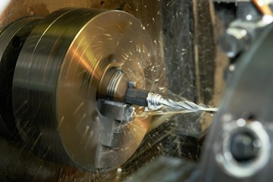
Boring is primarily used for finishing large, cored holes in castings or pierced holes in forgings. Most tools are similar to those in traditional, external turning, but cutting angles are particularly critical due to chip flow concerns.
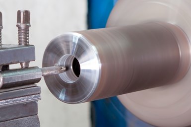
Rigidity is also paramount to productivity in boring. The diameter of the hole and the need for additional chip removal clearance directly influence the maximum size of the boring bar. Practical overhang for steel boring bars is four times their shank diameter. Exceeding this limit compromises the metal removal rate due to loss of rigidity and increased vibration possibility.
Diameter, material modulus of elasticity, length and load on the beam influence rigidity and deflection, with diameter providing the largest effect and length the second-largest. Increasing the bar diameter or shortening length will notably increase rigidity.
Modulus of elasticity is specific to the material being used and does not change with heat treating. Steel is the least stable at 30,000,000 psi, with heavy metal at 45,000,000 psi and carbide at 90,000,000 psi.
All the same, these are high numbers for stability, and steel shank boring bars offer satisfactory performance for most operations up to a length/diameter ratio of 4:1. Tungsten carbide shank boring bars perform well up to a length/diameter ratio of 6:1.
Cutting Tool Geometry in Boring
Radial and axial cutting forces in boring are influenced by the lead angle. The increased axial force of a small lead angle can be especially useful in reducing vibration. As the lead angle increases, radial forces increase and raise the forces perpendicular to the direction of the cut, contributing to vibration.
Recommended lead angles to control vibrations in boring are between 0 degrees and 15 degrees (in the imperial system. In the metric system, this would be 90 degrees to 75 degrees). At a lead angle of 15 degrees, radial cutting forces are almost twice as high than at a 0-degree lead angle.
Positive rake angle cutting tools are preferable for most boring operations in order to reduce cutting forces. However, the smaller clearance angles of positive rake angle tools require operators to plan for the possibility of contact between the tool and the workpiece. It is especially important to ensure an adequate clearance angle when boring small diameter holes.
Radial and tangential forces in boring operations increase as the nose radius increases, but these forces are also subject to the lead angle. The depth of cut of boring operations can alter this relationship: if the depth of cut is greater than or equal to the nose radius, lead angle determines the radial forces. If the depth of cut is less than the nose radius, the cutting depth itself increases the radial forces. This problem makes it especially important operators use a nose radius smaller than the cutting depth.
For recent topics in turning, visit the MMS Turning Machines information zone.


Related Content

Addressing Manufacturing Challenges with Automation
GrayMatter Robotics’ Physical AI robotic cells for manufacturing offer immediate impact and results.
Read More
The Future of High Feed Milling in Modern Manufacturing
Achieve higher metal removal rates and enhanced predictability with ISCAR’s advanced high-feed milling tools — optimized for today’s competitive global market.
Read More
4 Commonly Misapplied CNC Features
Misapplication of these important CNC features will result in wasted time, wasted or duplicated effort and/or wasted material.
Read More
Shoulder Milling Cuts Racing Part's Cycle Time By Over 50%
Pairing a shoulder mill with a five-axis machine has cut costs and cycle times for one of TTI Machine’s parts, enabling it to support a niche racing community.
Read More