
Probing For Process Improvement
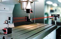
Advances in machine accuracy and probing technology make on-machine inspection a powerful tool for automating and speeding part processing.


To use machine probing for process control and final part inspection, the machine tool itself must be process-capable.
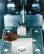
In the photo above, Western Industrial Tooling (Redmond, Washington) uses probing to measure complex features and “buy off” a tiny EDM electrode used to machine molds for phone connectors. Strain-gage sensors reduce the probe’s trigger force and pre-travel, increasing precision.
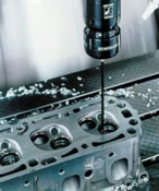
In-process inspection is especially desirable for makers of complex, high-value 3D parts, such as these cylinder heads for NASCAR racing produced by CNC Cylinder Head (Pinellas Park, Florida).
There is a relatively inexpensive and easy-to-use machine tool accessory that can deliver significant reductions in production time and cost. That accessory is the machine tool probe.
Long used mainly for setup, on-machine probing is gaining widespread application for process improvement—automating and speeding part processing, even eliminating parts of the process. The growth is being driven by shifts to flexible machining, shorter leadtimes, tighter accuracy specifications and automated processing—all areas where on-machine probing yields time, quality and productivity improvements.


A traditional objection to on-machine probing—that it diverts machine time away from making chips—can be overcome by measuring productivity in terms of total in-process time, rather than machining cycle time. The view that probing steals machining time focuses on the 10 seconds or so that checking a part feature can require. However, this focus overlooks the fact that checking the part off-line, a step that probing may make unnecessary, can impose the need for additional part handling and another setup, adding to in-process time (not to mention introducing the potential of fixturing error).
Considered in the overall context of part processing time, rather than simply machining time, probing can produce vital gains in processing efficiency and manufacturing productivity. In flexible machining operations with small batch sizes, the time that probing saves up front on setup, and at the end on inspection, more than offsets total probing time.
Machine tool probing potentially makes sense at nearly every stage of the process:
- Setup. Used to locate the part automatically and establish a work coordinate system, probing cuts setup time, increases spindle availability, lowers fixture costs and eliminates nonproductive machining passes. On complex parts, 45 minutes of fixture alignment can be replaced by 45 seconds of probing—performed automatically by the CNC.
- Fail-safe operation. Data such as work coordinate updates, tool geometry changes, part measurement, and so on, can be automatically determined by the CNC after the successful completion of a probing cycle. This eliminates costly errors resulting from manually mis-keying or miscalculating the information.
- Part identification. Probing can determine that the correct part has been loaded during automated part processing. This part ID procedure lets the CNC call up the correct program, while delivering an added level of protection for the machine tool.
- Toolsetting. In addition to the spindle-mounted probe, another type is the table-mounted toolsetting probe. A toolsetting probe is an economical solution for on-machine verification of tool geometry and condition. The toolsetting probe can automatically set length and diameter, and identify broken tools. Once tool condition is known, a “sister” tool may be called or an operator message may be issued.
- In-process control. This uses the spindle-mounted probe to monitor size and position of machined features during the cutting process. A probe can be programmed to monitor the process and automatically apply cutter compensation or adjust work coordinates — all helping to eliminate scrap, reprogramming, or potential rework. What results is a closed-loop process that requires no on-the-fly operator intervention.
- First-off part inspection. Probing can make first-part inspection seamless and automatic. Probing eliminates the delays and lost spindle time for manual inspection, especially when the operator needs to tear down the setup to inspect the part, then reinstall it for any compensating cuts.
- Final inspection. Used to inspect parts after machining, probing reduces the need for offline inspection and in some cases can eliminate it altogether. Through the use of a traceable artifact, probing cycles can be structured to compare final dimensions of a machined feature to a known dimension for the machine-resident article. When making this comparison, the CNC can determine if the specified machining tolerances were actually achieved. Based on these results, an intelligent decision can be made: proceed with machining, adjust tool geometry, modify work coordinate system, and so on.
Using on-machine probing to “buy off” a part while still fixtured can greatly shorten in-process time, eliminating the need to remove clamps, transport the part to a CMM, refixture the part, account for thermal effects and re-establish datum points before measuring. Inspecting on the machine is particularly beneficial with large, expensive workpieces such as molds or large aerospace parts that can be difficult and time-consuming to move.
The most expensive, non-value-added process in most shops is piece part inspection. When the machine tool is well-maintained, automated probing can assure that the process stays in control and the parts coming off the machine stay on spec. That’s why keeping the machine well-maintained is also essential if piece-part inspection is to be reduced.
Establish Machine Capabilities
Today’s standard machine tools deliver accuracy and repeatability approaching levels formerly available only on CMMs. In addition, technology advances are making these machines easier to maintain.
Test and calibration technology are now available—and affordable—to enable shops to ensure the accuracy and health of their machine tools. Telescoping ballbars are readily affordable by virtually any shop. A well-stocked toolbox should also contain either electronic levels or a good set of precision machine levels. Plants and large shops increasingly maintain their own laser interferometers and electronic levels, while rental equipment and diagnostics services are commercially available to small shops from various sources.
Shops investing in the health of their machines can do many more things with their capital equipment. When the ability of the machine tool to move a probe around accurately and repeatably can be trusted, the shop can inspect the part immediately after cutting it without extra handling and refixturing.
In order to move toward 100 percent good parts, it is essential to understand all process variables. This is a requirement of ISO 9000 and QS 9000. A shop must be able to document the process capability and the accuracy of its machines. One way to do this is to inspect them to a nationally recognized and accepted standard, such as ISO 230 or ASME B5.54. Both call for a ballbar and laser to be used with a recommended procedure for checking machine tool accuracy.
The purpose of these standards is not to specify an accuracy the machine must meet, but to find out its process capability or what accuracy level it can meet. The part print dictates the accuracy your machine must have to make good parts—that is, where to set the accuracy bar. Testing tells you how high your machine can jump. As long as the machine can top the bar, you have process capability.
The industry trend is to calibrate the machine on need, not time. There is no reason for the maintenance department to pull a perfectly good machine out of production for calibration. Let the ballbar and the accuracy of the parts determine when something has gone awry. Meantime, run production!
More Accurate, Versatile and Affordable Probes
The growth in on-machine probing is also being driven by technology advances that make machine tool probes more accurate, more productive, easier to use, and easier to afford. To illustrate this, here are four relatively new probe developments:
- Strain-gage probe. This probe has a strain-gage bridge in place of a mechanical switch to minimize pre-travel variation. The effect on probing precision is to provide levels of performance never before possible on a machine tool probe—that is, unidirectional repeatability of 0.5 micron with a 50 mm stylus. Strain-gage sensors deliver low trigger force and a uniform 3D triggering pattern. This allows faster probing on complex parts while eliminating the programmer’s requirement to compensate for lobing characteristics that can affect probing precision. A multi-channel digital filter recognizes and ignores unintended triggers resulting from machine vibration and high acceleration/deceleration forces. This makes the strain-gage probe particularly suited to high-speed machining centers.
- High-power optical system. This new method of transmission, available for strain gage or conventional switching probes, extends transmission range to 12 meters, while omni-directional signal coverage permits transmission from any spindle orientation. The new system uses a high-power infrared transmitter, modified optical receiver, and machine interface with high speed digital switch. It is designed for applications requiring extended-range transmission, environments which are not conducive to the use of RF transmission, or tilt-spindle applications that position the probe at complex vectors that traditionally result in loss of an optical signal. The system is particularly suited to very large five-axis machine tools, such as gantry profilers in the aerospace industry. It provides the high positioning accuracy needed to meet aerospace requirements that are driving the industry to automated “shimless” assembly.
- Radio probe system. This new probe takes radio technology out of the crystal age with 40 user-selectable channels. It extends the advantages of automated on-machine probing to applications not suitable for optical transmission. Unlike single channel systems that require crystal replacement to change a channel, this probe permits channel selection using a simple optical transmission link similar to the setup procedure for a garage door opener.
- Non-contact toolsetting. A new laser-based toolsetting system takes the complexity—and cost premium—out of non-contact toolsetting. A solution for high-speed, high-precision tool setting and broken tool detection, the laser-based system rapidly measures tool length and diameter at normal speeds to minimize impact on cycle times. Laser checking at working spindle speeds identifies errors caused by clamping inconsistencies and radial run-out of the spindle, tool and toolholders—not feasible with static toolsetting systems. The toolsetting system also performs broken tool detection “on the fly,” even at maximum rapid traverse, to minimize out-of-cut time.
As the tool moves through the laser beam, system electronics detect when the beam is broken and issue an output signal to the controller. The system accurately measures tools as small as 0.2 mm diameter anywhere in the beam. The system triggers when the laser beam is broken beyond a 50 percent threshold by the tool being checked. The non-contact toolsetting system uses a visible-red diode laser proven reliable in machining conditions. The visible-red laser operates at 670 nm wavelength at low-power output of less than 1 mW.
Advanced electronics permitting simplified design for the first time make non-contact toolsetting an affordable alternative to contact systems. The design avoids the mechanical elements and potentially complex installation of other toolsetting systems—the brackets and actuators with contact-based systems, and the problems with shutters, switches and solenoids on other non-contact designs. A protection system features positive internal air pressure that supplies a continuous stream of air through the laser beam apertures to keep out contaminants.
The Operator’s Gage
Advances in machine tool accuracy and probing technology make machine inspection viable for process control by allowing a machine to be used to verify the accuracy of parts it machines. Once a machine tool’s performance as a measuring instrument has been established, the probe becomes the operator’s CNC gage.
This represents a fundamental change in the way inspection is performed. Rather than a postprocess check performed off-line on parts after machining, probing on the machine makes inspection part of the process, as well as a powerful process improvement tool for machining parts to spec in the shortest possible time. MMS
About the author: Dave Bozich is business manager, machine tool products, for Renishaw, Inc.


Related Content

Determining Out-of-Roundness at the Point of Manufacture
George Schuetz, Mahr Inc.’s Director of Precision Gages, offers these techniques for measuring roundness on the shop floor.
Read More
6 Machine Shop Essentials to Stay Competitive
If you want to streamline production and be competitive in the industry, you will need far more than a standard three-axis CNC mill or two-axis CNC lathe and a few measuring tools.
Read More
5 Things CNC Operators Must Know About Sizing Adjustments
For CNC operators, sizing adjustment is an essential skill. Keep these points in mind when training new CNC users.
Read More
Choosing the Correct Gage Type for Groove Inspection
Grooves play a critical functional role for seal rings and retainer rings, so good gaging practices are a must.
Read MoreRead Next

3 Mistakes That Cause CNC Programs to Fail
Despite enhancements to manufacturing technology, there are still issues today that can cause programs to fail. These failures can cause lost time, scrapped parts, damaged machines and even injured operators.
Read More
The Cut Scene: The Finer Details of Large-Format Machining
Small details and features can have an outsized impact on large parts, such as Barbco’s collapsible utility drill head.
Read More
