
X-Ray Part Scanning as a Dimensional Measurement Process
Data-driven manufacturing gets a boost with a new class of x-ray inspection equipment that outputs a digital twin of a machined part, including complete 3D representations of internal and external dimensions.


This bone plate, a bit larger than a postage stamp, is ready for X-ray inspection. The beam emitter is behind it. All photos courtesy of Zeiss.
CT scans enable a physician to “see” and look around inside the human body for physical conditions like tumors or aneurysms. Similarly, industrial CT scanners enable manufacturers to “see” inside a workpiece — generally, to spot voids in castings, cracks in welds or other unwelcome abnormalities. Although both applications date back nearly half a century, the latest X-ray based CT equipment is moving well past visual imaging. Manufacturers are now capable of measuring the internal features of a workpiece, including features that could not be measured any other way, to nanometer accuracy. What may not be well recognized in industrial QC circles is that the latest X-ray inspection systems also capture the dimensions of external part geometry. In essence, the CT scan of a workpiece can now provide a full, 3D digital representation of the entire part — the inside and the outside in a near perfect relationship as a solid model. More importantly, the relationship of this 3D representation to the physical workpiece is so precise that the 3D representation also becomes a digital twin. As a virtually identical stand-in for the actual part, this digital twin has numerous uses that give the manufacturer numerical data for making sound, reliable decisions on an unprecedented level.
“The image is a CAD model, but it is constructed of scanned data elements in high resolution rather than the theoretical 3D geometry created by the designer or engineer,” Legacy says.
In short, X-ray inspection has become an important component of modern metrology. “For the right applications, X-ray inspection is a practical alternative to other measurement techniques, offering technical and economic advantages that make it compelling for a range of machining companies and manufacturers,” says Kevin Legacy, head of X-Ray North America at Zeiss Industrial Quality Solutions in Wixom, Michigan. “We are seeing a groundswell of adopters of this technology, especially among medical manufacturers and producers of small precision parts in aluminum and titanium,” he adds. Legacy also sees interest in X-ray inspection growing for another reason: its potential to promote concepts such as the digital twin that can enhance integrated, data-driven manufacturing for any machining company.


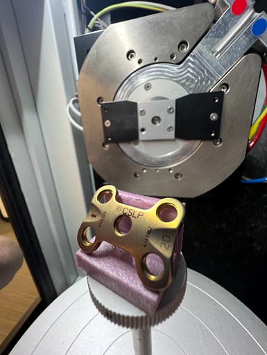
For scanning, this titanium bone plate is placed on a simple holder on a rotary table, which is positioned between the X-ray emitter and the detector panel.
A Computed Tomography CMM?
Whether for industrial or medical applications, computed tomography (the ‘CT’ in CT scan) refers to the method of generating a 3D image by compiling a series of cross-sectional views (slices) of an object (“Tomos” is the ancient Greek word for slice or section). The 3D image that is the vital output of a CT scan is an integrated compilation of the cross sections.
In industrial applications, X-rays are a common means of producing these cross-sectional views. Legacy likes to use the term CT CMM — computed tomography coordinate measuring machine — to describe X-ray equipment specifically designed for metrology. Although using this so-called CT CMM is a non-tactile, non-destructive process, it has important similarities to the process of inspecting and measuring a workpiece on a CMM with a conventional trigger touch probe, as well as similarities to the process of inspecting a workpiece on an optical system or laser scanning device.
X-ray inspection is a non-contact, non-destructive scanning process, Legacy emphasizes. The high energy beams of light do not alter the workpiece in any way. Because no touch probe stylus is used, contact forces do not cause distortions or deflections that might affect measurements.
“All of these devices measure a part. They give us the dimensions of various part features. In fact, X-ray inspection often provides the measurements with greater ease, in less time and to higher precision,” he says, acknowledging that each class of metrology devices has its niche, that is, a specific set of “right applications.”
According to Legacy, a good way to see where X-ray inspection fits in starts with an understanding of the basics of its technology. “The two main steps are easy to grasp. The part is scanned; then the data from the scan is interpreted in the system’s software,” he explains. As noted, before, the result of that interpretation is a 3D file, a CAD-like image with the dimensional measurements of its features called out. “In fact, the image is a CAD model, but it is constructed of scanned data elements in high resolution rather than the theoretical 3D geometry created by the designer or engineer,” Legacy says.
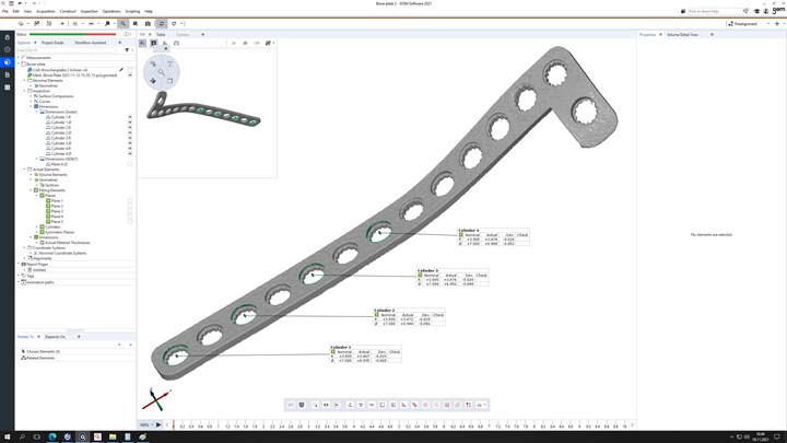
The results of scanning a workpiece such as a medical bone plate include 3D digital images representing a solid model of the part. The inset shows the precise measurements of part features derived from this digital model.
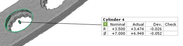
Inset.
X-ray inspection involves casting a beam of high-energy light waves over and across the workpiece. These beams pass through the workpiece to reach a detector, and beam energy levels are recorded as numerical values. Because the varying volumes of the workpiece material block varying amounts of beam energy, these numerical values recorded by the detector also vary correspondingly.
The most advanced X-ray inspection devices use cone beam scanning, Legacy says. Beams from the emitter are arrayed in a cone shape and projected onto the workpiece as it rotates on a motorized table. The cone of X-rays produces a large number of 2D images recorded at high speed by the detector.
“Here is where the computing part of computed tomography comes in,” Legacy explains. The processing speed of today’s computers and their ability to record and access large databases and the computational power of efficient analytical algorithms combine to generate the 3D representation of the scanned workpiece. This representation can be viewed as a visual image to check the condition of part features and detect problems by eye. This may be all that is necessary to cull defective castings in a batch coming off the pouring line in the foundry, for example.
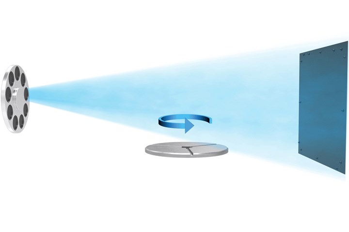
As the table rotates, beams from the emitter (left) create a series of cross-sectional views of the workpiece that are captured digitally by the detector (far right).
Part Measurements, Please
Much more useful is having dimensional measurements of internal and external part features. For dimensional measurements of scanned workpiece features, the software basically “counts the pixels” and translates them into the equivalent standard units for length, diameter and so on. As Legacy explains, the precision of these measurements depends largely on the resolution and total number of cross-sectional snapshots.
In basic applications, critical part dimensions easily can be compared to nominal values as part of a quality check. The numerical data can be used to spot out-of-tolerance material conditions in an individual workpiece, or to monitor trends by analyzing data sets from a series of sample parts.
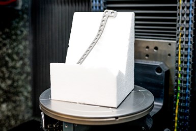
X-ray inspection is a non-contact, non-destructive scanning process, Legacy emphasizes. The high energy beams of light do not alter the workpiece in any way. Because no touch probe stylus is used, contact forces do not cause distortions or deflections that might affect measurements. Parts do not need to be clamped or fixtured for scanning, although Legacy says that a simple holder fabricated in rigid polystyrene foam is recommended for operator convenience and fast, consistent positioning (the software precisely orients and aligns the 3-D representation automatically). Likewise, since a touch probe does not have to be maneuvered around a workpiece, clearance planes and possible collisions are not a concern for the X-ray inspector.
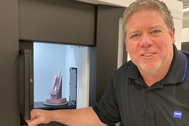
Kevin Legacy has opened the door of a Zeiss X-ray scanning machine to reveal a medical part in a rigid plastic film holder, ready for scanning. No clamping fixtures are required. In operation, the machine’s enclosure is sealed to completely contain the energy from the scanning process.
Another advantage of noncontact measurement is that it is not limited by the size of a trigger touch probe stylus. “The smallest tip for a CMM stylus is 0.3 mm in diameter. In comparison, an X-ray beam is not limited by tooling constraints. As long as the system configuration produces sufficient resolution to ‘see’ the feature, the software will be able to measure it,” he says.
The weakness of X-ray inspection is the relative inability of the light energy beams to pass through dense cross sections of materials such as cast iron, tungsten, precious metals and certain alloys. “The amount of energy involved in ‘punching’ through cast iron, say, makes X-ray inspection impractical for most QC labs in factories or job shops,” Legacy says. And there are many types of parts for which the choice of the best inspection technique hinges on other factors, such as throughput speed, the investment required or inspection reporting requirements.
Machined parts in aluminum and titanium, however, have proven to be some of the most successful applications for X-ray inspection. Titanium bone plates, bone screws and dental implants are typical of the parts for which X-ray inspection is ideally suited.
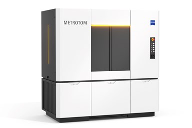
The Metrotom 6 Scout from Zeiss is an example of an X-ray scanning system appropriate for inspecting high-precision medical components and similar workpieces. The machine’s footprint is roughly 3 foot by 6 foot, comparable to a small CNC lathe. It is suitable for use on the shop floor or in a QC lab.
Inspecting An X-Ray Inspection Machine
If bone plates, bone screws and other small, high value workpieces are suitable for X-ray inspection, what kind of X-ray system would be most appropriate for this application? Legacy believes that the Zeiss Metrotom 6 Scout is a likely candidate. A quick look at the system, he says, helps a machining company understand a real-world example of the hardware and software that embodies this technology.
In size and outward appearance, this unit resembles a small, fully enclosed lathe or other piece of production equipment that can be installed on the shop floor or in a typical QC department. With the front of the unit’s enclosure removed, the X-ray emitter can be seen on the left, the detector panel on the right and the inspection table in between. The table has five-axis positioning to put the workpiece in the best spot to produce high-contrast, high-resolution measurement results and the sharpest image for visualization.
“This is an exciting development in manufacturing and we are only now glimpsing some of the possibilities,” Legacy says. For example, checking the virtual fit of a bone plate or implant component to a CT scan of a medical patient’s body parts can improve surgical results.
The programming system for the unit, Calypso or GOM Volume Inspect, is the same proprietary software that programs Zeiss CMMs. “A user familiar with this software can adapt quickly to programming an X-ray inspection routine, although any experienced CMM programmer will catch on quickly,” Legacy predicts. He says that, in essence, four parameters require input for a scan. These are voltage and amperage settings for the X-ray emitter to achieve proper power and intensity of the radiation beam, the number of images to capture during the scan and the exposure time for each image.
Legacy estimates that a trained user can create a program in about 15 minutes, depending on the complexity of the part and number of features to be measured. Typical scan time for a single part is 2 to 3 minutes, in which time the rotary table makes one full rotation. Legacy also notes that Zeiss X-ray inspection systems such as the Scout can be calibrated using protocols traceable to national standards at the same intervals as appropriate for a CMM.
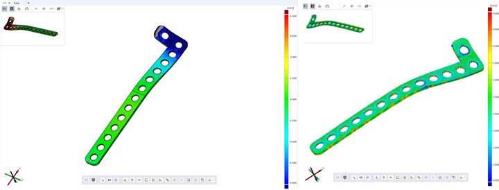
X-ray scanning can analyze more than workpiece dimensions. The display to the left shows conformance to part volume. The display to the right shows how well the part’s wall thickness conforms to the nominal tolerance band. Color coding indicates the extent to which deviations have occurred.
Sizing Up Scan Results
Legacy stresses that the representation of the workpiece that results from a CT scan is quite different from the data collected by a CMM with a touch trigger probe. Whereas the CMM collects discrete data points derived from the X, Y and Z axis coordinates at the tip of the stylus, scanning yields a collection of 2D cross-sectional images that are combined by the system’s software to create a 3D representation. “This 3D representation is a solid model with all of the same kind of information contained in a solid model created by CAD,” Legacy says.
Using X-ray inspection as a sophisticated metrology gage is just the tip of the iceberg, Legacy says. Having a 3D digital model of an actual workpiece makes numerous modes of further analysis possible. A user may want additional analysis quickly as part of a quality control strategy such as statistical process control, for example. The scan also can be archived and retrieved for further analysis as needed. Likewise, archived scans can serve as a traceable record of a manufacturing process.
To help users get the most from scanning results, Zeiss acquired GOM GmbH of Braunschweig, Germany. GOM is now Zeiss’s arm for non-contact systems and software to analyze and interpret scanning results, Legacy explains. This software provides the digital tools for GD&T inspection and product manufacturing information (PMI) if available. It can determine wall thickness and part volume, including the volume of internal cavities or passages, and it can detect and quantify defects, such as porosity. Cross-sectional views provide detailed comparisons of actual part geometry to the nominal (including surface contours).
The solid model rendering of the scanned data is proving to be a boon in other ways. For example, as a digital twin of the actual workpiece, the scan creates new opportunities for a manufacturer. “This is an exciting development in manufacturing and we are only now glimpsing some of the possibilities,” Legacy says. For example, checking the virtual fit of a bone plate or implant component to a CT scan of a medical patient’s body parts can improve surgical results. Digital twins of mating joint replacement components can be tested for fit and function.
Checking assemblies of miniaturized instrumentation is another possibility. Digital twins may be useful in virtual reality scenarios to fine-tune assembly operations or robotic automation. Reverse engineering also can be enhanced with judicious use of digital twins.
“An X-ray beam is not limited by tooling constraints,” Legacy says. “As long as the system configuration produces sufficient resolution to ‘see’ the feature, the software will be able to measure it.”
An X-ray in Your Future
Legacy believes that X-ray inspection will grow rapidly in the near future. “As a versatile, highly flexible method of dimensional measurement, industrial X-ray systems will continue to enlarge the set of applications that are right for it,” he says. And the technology will continue to advance, especially in its computational speed and power. At the same time, interest in and the understanding of digital twins as an essential element of data-driven manufacturing will also progress.
At the moment, the most important thing is to build a greater awareness of X-ray scanning as an option for measuring parts and to think imaginatively about its potential to connect product data with process data in data-driven environments.


Related Content

4 Ways to Establish Machine Accuracy
Understanding all the things that contribute to a machine’s full potential accuracy will inform what to prioritize when fine-tuning the machine.
Read More
Understanding Errors In Hand-Held Measuring Instruments
Different instruments (and different operators) are prone to different errors.
Read More
Building an Automation Solution From the Ground Up
IMTS 2022 provides visitors the opportunity to meet with product experts to design automation solutions from scratch.
Read More
Choosing the Correct Gage Type for Groove Inspection
Grooves play a critical functional role for seal rings and retainer rings, so good gaging practices are a must.
Read MoreRead Next

CT Scanning Moves from Lab to Production Line
In addition to raw computing power, new microfocus source designs and intuitive software make this technology ready for the production line.
Read More
Inspection With X-Ray Vision
Could detecting and quantifying the internal flaws of complex parts be as easy as operating a microwave oven? Kevin Legacy, manager of computed tomography (CT) and engineering at Carl Zeiss IMT Corporation, thinks so. He compares the manufacturer's Actis line of industrial CT systems to the one-button operation of the kitchen appliance.
Read More
Reverse Engineering: A Basic How-To
An inspection specialist imparts principles for successfully going about the reverse engineering process with 3D scanning equipment.
Read More