How to Choose the Right Tool for Milling Titanium
Milling titanium is different from other metals because of the risk of heat build-up. Thanks to the metal’s low thermal conductivity, overly aggressive milling may even pose a risk of combustion. With titanium, in other words, there may be more than one reason why the cutting speed can’t be increased. And yet the speed of production still can be increased.
.jpg;width=70;height=70;mode=crop;format=webp)

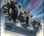
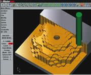
Where cutting speed is limited, plunge roughing can offer an effective way to increase the metal removal rate. In plunge roughing, the milling tool feeds in the Z direction. All of the tools shown at top left might be used in this way. The approach not only engages more cutting edges at once, but it also takes advantage of the stiffest axis of the machine. The CAM illustration of plunge roughing is courtesy of Mastercam/CNC Software.

This tool has axial rake angles that vary from one cutting edge to the next. This variation inhibits chatter, potentially allowing the tool to mill more productively.
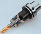
HSK and shrink fit (both of which appear on this toolholder) can make the process stiffer. The reduced potential for chatter can increase the metal removal rate.
Milling titanium is like milling other hard-to-machine metals in that a small increase in cutting speed can lead to a big increase in edge wear.
Milling titanium is different from other metals because of the risk of heat build-up. Thanks to the metal’s low thermal conductivity, overly aggressive milling may even pose a risk of combustion. With titanium, in other words, there may be more than one reason why the cutting speed can’t be increased.


And yet the speed of production still can be increased. A shop milling titanium can raise its metal removal rate even while the cutting speed stays constant. Accomplishing this does not have to involve a more powerful or higher-end machine tool, but it does require tooling that can take advantage of the power of the existing machine. It also requires tooling that can compensate for any shortcomings the machine may have when it comes to rigidity.
One company that has studied titanium milling is cutting tool supplier Kennametal. And one advisor in this company who has consulted on many titanium milling applications is Brian Hoefler, product manager for milling. This article is based on his experience and recommendations.
Why is milling titanium worth the attention? There are at least two reasons. First, the material is used for high-end parts—not just components used in an aircraft’s frame and engine, but also medical parts, for example. Shops able to thrive in the United States increasingly will migrate toward higher-end work, meaning that a growing percentage of U.S. shops will encounter this material.
That’s one reason. Another, broader reason for covering titanium milling relates to the procedures for machining effectively when the material is difficult to cut or the available speed is low. Not every shop has access to high spindle speeds and feed rates. What do you do to achieve higher productivity when raising the cutting speed is not option?
Weigh Wear Resistance Against Toughness
The fundamental choice of cutting tool material should be the first consideration, Mr. Hoefler says. Carbide might be the right choice. But shops are often so accustomed to viewing carbide as the superior cutting tool material that they routinely choose it for all difficult jobs. With titanium, newer generation high speed steel can be the better alternative.
The wear resistance that allows carbide to reach a high cutting speed comes at a price. That price is paid in “bulk toughness,” or the ability of the tool to resist fracturing and chipping. Carbide in general is more brittle than high speed steel.
This is significant in titanium milling, because it is generally not edge wear that causes the tool to fail in this material. Rather, it’s chipping or breakage that leads to failure. In addition, heat build-up may make it impossible to take advantage of the cutting speed that carbide makes available. These two factors both suggest that the trade-off in toughness may not be worth making. A tougher tool—a high speed steel tool, that is—can take a deeper cut without fear that shocks will cause the edges to chip. Particularly on a less rigid machine tool, this more forgiving tool material can let the shop realize a higher metal removal rate through depth of cut instead of through speed.
But even this material presents a range of choices. Too few shops realize that there is more than one kind of high speed steel. While commodity high speed steel tools are made through a process that involves heat treatment, the alternative—powder metallurgy tooling—can be manufactured so that the steel has a more uniform structure with more closely controlled properties. Powder metallurgy tools are more expensive, but they generally offer better performance.
Heat Resistance
Sometimes carbide is needed. Low-radial-immersion cuts, for example, can allow a surprisingly high speed (see shaded box titled "10 Percent Radial Depth? Double The Speed" above). In cuts such as these, it’s not just wear resistance but wear resistance at high temperatures that’s important. That requirement suggests a coated carbide tool.
Mr. Hoefler says titanium aluminum nitride (TiAlN) coated carbide is usually the best choice for machining titanium. Out of the handful of basic cutting tool coating types, TiAlN is clearly the best at maintaining its integrity and properties as the temperature in the cut gets hot. In fact, heat actually drives this coating’s protection. Aluminum that is liberated from the coating through the energy of machining helps to form a protective layer of aluminum oxide. This layer reduces both thermal transfer and chemical diffusion between the tool and the workpiece. Coatings coming soon add even more aluminum to encourage this reaction. (See the shaded box below.)
When TiAlN is not the right choice, the reason why relates to vibration. Titanium carbo-nitride (TiCN) is a stronger coating that offers better resistance to micro-chipping. “When you’re using an indexable insert, and you’re taking a heavier cut on a less rigid machine, try TiCN—this may be the better choice,” Mr. Hoefler says.
Number Of Effective Edges
Even when the speed, the chip load and the depths of cut are all fixed, productivity can still be improved. To raise the metal removal rate, increase the number of effective edges.
On a helical mill, for example, choose the tool with the finest pitch possible. (A corncob tool may also work.) Counting edges in this way creates one more reason to consider high speed steel, because high speed steel generally can offer more cutting edges than a comparable tool that uses carbide.
Another way to achieve a higher number of effective edges is to take milling in a different direction. Through “plunge roughing,” a shell mill, or another suitable milling tool, is fed into the work along the Z axis as if it were a drill. The parallel plunges are programmed to overlap, so the cutter is never completely surrounded by material and the chips have room to escape.
This approach can only be used for roughing, because the adjacent passes leave scallops between them that have to be milled away later. But because plunge roughing engages a larger number of the tool’s cutting edges, the feed rate in inches per minute can be increased while the chip load remains constant. Feeding in Z also takes advantage of the machine’s stiffness, because the various connections along the spindle that would tend to deflect along X or Y (such as the toolholder interface) are compressed in the Z direction. Along Z, the machine is more rigid. That means it may be possible even to increase the chip load.
Mr. Hoefler says, “Plunge roughing can be a very productive approach to material removal in high-strength metals. I don’t think enough shops today are taking advantage of this.”
Vibration Elimination
Potential for deflection is also important because of another, more serious problem—chatter. Where chatter is concerned, milling titanium seems to offer the worst of both worlds. On the one hand, high forces are involved, making significant chatter more likely. On the other hand, high spindle speeds generally are not involved, making it impossible to find some “sweet spot” rpm value that can tune the chatter away.
Chatter, in fact, will decide the productivity of most titanium milling applications. The maximum achievable metal removal rate will occur not at the point where the horsepower is maxed out, but at the point where significant chatter begins. That’s why it’s important to construct the process so that it impedes chatter as much as possible. Mr. Hoefler suggests any and all of these considerations:
- Stiffness. The interface between the tool and the toolholder, and the interface between the toolholder and the spindle, both need to be made as stiff as possible. For the tool interface, shrink fit offers a solution. For the spindle, an HSK interface can offer better stiffness than a conventional conical taper.
- Damping. A tool with an eccentric relief, or a “margin,” can offer process damping that wards off chatter. When the tool deflects, this eccentric relief comes in contact with the workpiece and rubs. Not all materials take well to the rubbing; aluminum tends to adhere. But in titanium, the margin can make for an effective shock absorber.
- Variable cutting edge spacing. This is an approach to tool design and chatter prevention that many shops may be unfamiliar with. Chatter results from the oscillation caused by the cutting edges hitting the work with a regular frequency. Some milling cutters useunequally spaced flutes to disrupt this regularity. Two cutting edges may be 72 degrees apart, while the distance to the next is 68 degrees and the distance to the edge after that is 75 degrees. The irregular spacing aims to avoid chatter by preventing a steady frequency from taking hold. Another option, patented by Kennametal, exploits a varying axial rake angle to achieve a similar vibration-disturbing effect.


Related Content

Understanding Errors In Hand-Held Measuring Instruments
Different instruments (and different operators) are prone to different errors.
Read More
7 CNC Parameters You Should Know
Parameters tell the CNC every little detail about the specific machine tool being used, and how all CNC features and functions are to be utilized.
Read More
6 Steps to Take Before Creating a CNC Program
Any time saved by skipping preparation for programming can be easily lost when the program makes it to the machine. Follow these steps to ensure success.
Read More
Understanding Swiss-Type Machining
Once seen as a specialty machine tool, the CNC Swiss-type is increasingly being used in shops that are full of more conventional CNC machines. For the newcomer to Swiss-type machining, here is what the learning curve is like.
Read MoreRead Next

Plunge Roughing Right Now
This mold shop makes plunge roughing work using the kind of machine and the kind of tooling it’s been using all along. In other words, this shop achieved a faster metal removal rate just by changing direction.
Read More
3 Mistakes That Cause CNC Programs to Fail
Despite enhancements to manufacturing technology, there are still issues today that can cause programs to fail. These failures can cause lost time, scrapped parts, damaged machines and even injured operators.
Read More