
Tips for Anticipating Hole Conditions
When measuring an ID with an indicating plug gage, it is OK to slow down to learn more about the hole being measured and explore for extraneous conditions.


For most users, a fixed-body indicating plug gage, whether mechanical or pneumatic, is probably the easiest gage to use to get a fast, high-precision and accurate hole diameter. Simply insert the plug gage into the hole and read the deviation from the master to get the diameter.
However, the real advantage of these types of gages over an adjustable bore gage is that it is a lot easier and faster to determine hole conditions such as ovality, taper, hourglass or bell-mouth shape. All it takes is a further exploration of the bore.


The need for speed is certainly the cry of production manufacturing, but when measuring an ID with an indicating plug gage, it is OK to slow down just a little to learn more about the hole being measured. Take the time to explore for extraneous conditions, and should something be discovered, find the minimum diameter, as it generally will have the greatest effect when a shaft or cylinder is assembled to the bore.
First, simply rotate the plug at the same level in the bore, searching for the minimum and maximum conditions. This is easy to follow on an analog scale.
Hopefully, both readings are within the diameter tolerance. If not, this could indicate that something is awry with the manufacturing process. As mentioned above, it is probably a good idea to note specifically where the minimum diameter is located, as it may help fix or prevent future problems.
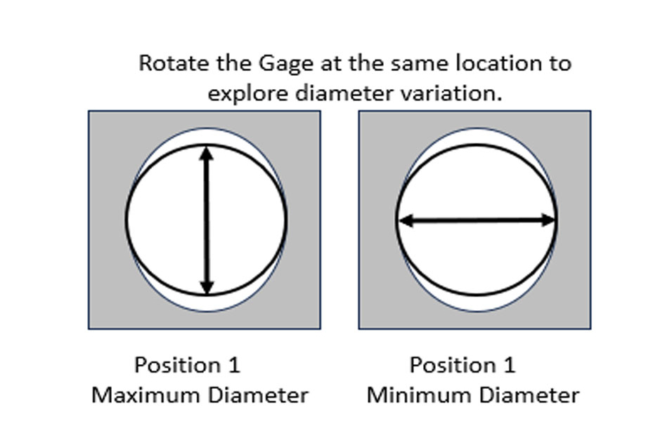
This diameter variation — the difference between the minimum and the maximum diameters — is often referred to as total indicator runout (TIR). With many digital indicators or bench amplifiers, there are built-in functions that can be used to “remember” this difference, so the operator does not have to manually calculate it.
Some confuse TIR with “roundness.” This is not the case; true roundness is different and defined in various international standards. However, some will use TIR at the point of manufacture as a trigger point for further measurements if the variation becomes significant compared to the diameter tolerance.
The next step in learning more about the hole is to start exploring it axially, say at three points along the length of the bore, and compare the three diameters. By comparing these diameters, it becomes easy to identify the presence of an hourglass, bell mouth or taper within the form of the hole.
As the figure below illustrates, the fixed plug gage can disclose these conditions with exploration at different depths. All of these are apt to appear within every hole manufactured, but the degree of the form error compared to the diameter tolerance is most important.
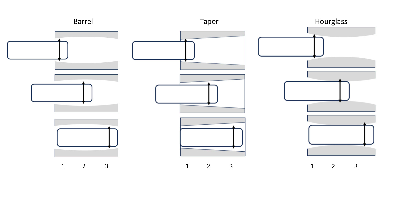
By exploring the hole axially at multiple locations, form errors such as hourglass, barrel or taper can be found. Photo Credit: Mahr Inc.
Some users will check these types of parts both radially and axially, exploring for the minimum and maximum values — or an overall diameter variation. As with Roundness, some might say this exploration is an indication of cylindricity. Cylindricity is a well-defined form parameter, and our exploration would not be the proper way to check this. However, use this as a trigger for further analysis if the variation is a large part of the diameter tolerance.
These small deviations in form are very critical in machine design, where surface contact is required for a shaft, and bearing is required. Conditions like the ones above would result in very uneven loading on the parts, which ultimately leads to vibration, faster wear and even premature breakdown. Taking a little extra time to explore critical components with a fixed plug bore gage can help to prevent these conditions.
But what if — even after a close inspection of the diameter and a thorough exploration of the part — there are some mating issues with the hole and its shaft? This may come down to other form errors where the two-point fixed plug gage just cannot measure.
A two-point fixed plug gage is great for inspecting for a minimum and a maximum diameter, as shown in the first figure above. The figure shows a hole that has two lobes; thus, it is a hole with an even number of lobes. A two-point plug can easily find this diameter variation.
But try to measure a hole that has an odd number of lobes — three, for example — and the gage is apt to show the part at the correct diameter and to have very little diameter for form variation. This is because a two-point plug gage cannot measure this condition.
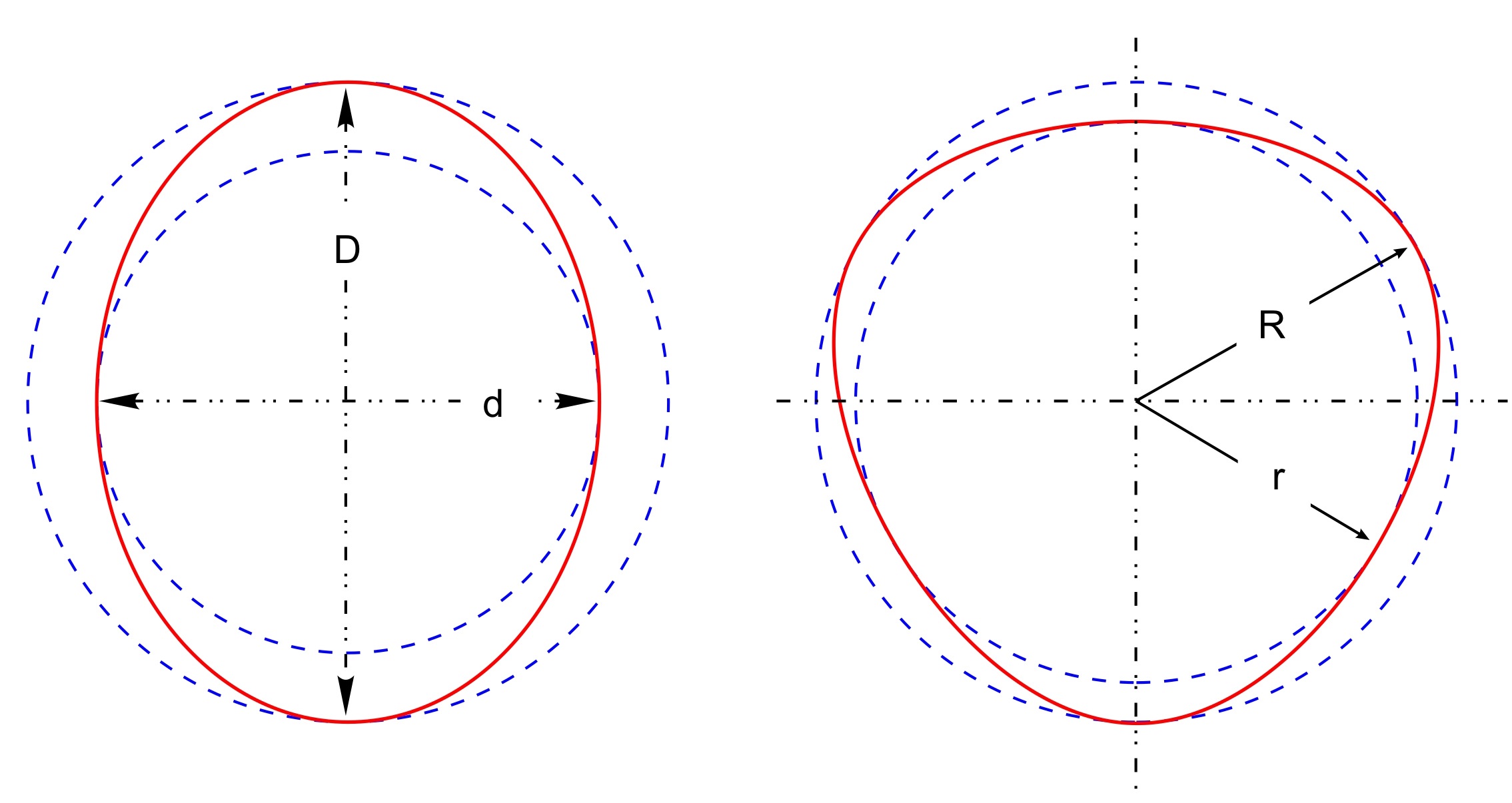
A two-point gaging system is best for even lobbing conditions, while a three-point gaging system is best for odd lobbing conditions. Photo Credit: Mahr Inc.
A fixed plug gage can provide more information about a hole than just the diameter at a single location. By making an effort to explore the hole, further details about the part shape can be made, as well as potential problems with mating parts.


Related Content

5 Things CNC Operators Must Know About Sizing Adjustments
For CNC operators, sizing adjustment is an essential skill. Keep these points in mind when training new CNC users.
Read More
Building an Automation Solution From the Ground Up
IMTS 2022 provides visitors the opportunity to meet with product experts to design automation solutions from scratch.
Read More
What Should Machinists Know About In-Machine Probing?
In-machine probing doesn’t reach the power of CMMs but can still be useful for pre- and mid-process control, as well as for “rough screening” of parts.
Read More
How to Choose the Correct Measuring Tool for Any Application
There are many options to choose from when deciding on a dimensional measurement tool. Consider these application-based factors when selecting a measurement solution.
Read MoreRead Next

3 Mistakes That Cause CNC Programs to Fail
Despite enhancements to manufacturing technology, there are still issues today that can cause programs to fail. These failures can cause lost time, scrapped parts, damaged machines and even injured operators.
Read More

The Cut Scene: The Finer Details of Large-Format Machining
Small details and features can have an outsized impact on large parts, such as Barbco’s collapsible utility drill head.
Read More