
Four Types Of Five-Axis Machining Centers
Different machines offer different approaches to rotary travel, and each design has its own strengths. Here's how they compare.
.jpg;width=70;height=70;mode=crop;format=webp)


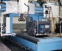
Fig. 2--A machine with two pivots in the spindle head. This design produces a five-axis machine that is particularly effective for parts that are rectangular instead of round.
.jpg)
Fig. 1--A machine with a rotary table axis and one pivot in the spindle. This five-axis machine design is effective for tall workpieces, and for cylindrical parts with holes around the periphery. The workpiece shown is a stainless steel compressor case.

.jpg)
Fig. 2--A double rotary table machine. This is the shop's best five-axis machine for the use of long tools or extensions. It is also effective for cylindrical parts with a ring of holes in one face.

.jpg)
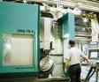
Fig. 4--A compact machine with a rotary table axis and a table trunnion. Having no pivots in the spindle head means this machine can take relatively deep cuts for its size. The shop bought this machine primarily as a means to apply five-axis machining economically to small parts. The workpiece shown is a shroud for a jet engine.
There was a time when General Tool Company (Cincinnati, Ohio) could win jobs on the basis of its pallet shuttles. While other shops had to let their machines sit idle during setup, General Tool could set up the next job while the current job was still in-work, cutting both costs and leadtimes. But that was years ago. Today, pallet shuttles are everywhere, and any serious competitor to this 250-employee contract manufacturer has also embraced the concept. So General Tool has turned its attention to developing other capabilities that can let it maintain its edge in setup time reduction. One of the most important of these is five-axis machining.
General Tool has been doing five-axis work for some time, but the company recently committed itself to a much larger investment in this technology. In just the past 15 months, the company has purchased three new five-axis machining centers, all from different builders. With these additions in place, the shop now calls upon machines offering four different approaches to the way the rotary axes pivot. Because each design has its own strengths, the range of options lets General Tool compete for a wide range of five-axis jobs.


For its customers in the aerospace, marine, and power generation markets, General Tool does "continuous" five-axis work. That is, machining with linear and rotary axes both feeding through the cut. However, the role of its five-axis machines goes beyond this swept surface milling. In fact, this work accounts for only about 20 percent of the jobs that call for one of the company's five-axis machines. In all of the other cases, the rotary axes reduce expenses just by reorienting the tool and/or workpiece outside the cut. This rotary movement saves setup time by letting the spindle reach opposing faces of the part in a single setup. It also saves tooling costs by letting a standard milling cutter, held at an angle, machine an angled surface that would otherwise require a custom tool.
That said, the proportion between continuous and position-only work may not always be 20/80. General Tool generally favors five-axis machines with full five-axis capability. So while the shop acquires five-axis machines primarily to streamline setup time, it is simultaneously adding more capacity with which it can bid for the more challenging five-axis work. And at this level of sophistication, there is a lot less competition for jobs.
In fact, one of General Tool's goals has been to achieve the capability to compete for the broadest variety of jobs possible. And where five-axis machining is concerned, meeting this goal means buying a variety of different machines. Linear axes may move in a comparable way on essentially every machining center model, but five-axis machines differ significantly in the ways they move the rotary axes. Some pivot the table, some pivot the spindle head, some do both. And every different pivoting strategy affects the type of work that machine can do well.
In other words, the right job for any conventional machining center is likely to be the right job for the next three-axis machine in the shop. But the right job for a given five-axis machining center may be the wrong job for a five-axis machine of another type.
Company industrial engineer Greg Kramer recently offered a perspective on the different types of five-axis machining centers General Tool uses. He says not one of these five-axis designs is inherently better than another. Instead, each different method of moving through the rotary axes makes that machine the best in the shop for processing a particular workpiece geometry.
Here is how Mr. Kramer characterizes the right jobs for four different five-axis machining center designs:
Design #1: Rotary Table + Pivoting Spindle Head
General Tool's newest machine to employ this particular five-axis design is a T-35 machining center from Cincinnati Machine (formerly Cincinnati Milacron; Cincinnati, Ohio). Like many other horizontal machining centers, this one (shown in Figure 1) places a 360-degree, B-axis rotary table beneath the workpiece. This table doesn't just index, it can also feed through a cut. The T-35 mates this rotary table to an A-axis pivot that feeds the spindle head from 30 degrees above horizontal to 30 degrees below. The enclosed machine offers a workzone 50 inches in diameter by 50 inches high.
The ideal part for this machine, says Mr. Kramer, is a cylinder with holes around its periphery—particularly angled holes. One example is a turbine housing. On a part like this, the same hole appears at various locations around the OD. When this is the case, a machine with this design can position itself from one hole to the next with a move in only one axis. Any other type of five-axis machine would move from one radial hole to another on a cylindrical part using moves in at least two axes, maybe more. But on a rotary table/pivoting head machine, the tool only has to be tilted to the correct angle for the hole one time, and the spindle head only has to be positioned in X, Y, and Z one time. Drilling a sequence of holes then becomes a matter of feeding in, retracting, and indexing only in B to reach the next hole.
The result is a more repeatable process. More axes of positioning would only compound the opportunities for positioning error to affect the move. That's why General Tool finds the one-axis move inherently more precise.
Another strength of this machine design relates to workpiece size. The fewer rotary axes move the workpiece (as opposed to the tool), the better the machine can accommodate large parts. This machine does rotate the work-piece in B, so the part's swing is limited in this axis. However, because this is the only workpiece pivot, the machine handles tall workpieces effectively. Five-axis machines placing both pivots at the table generally are limited to workpieces that are small relative to the linear travels. But the design of this five-axis machining center leaves the workpiece more fixed, allowing the machine to take on very tall cylindrical parts.
There is a trade-off, however. Any pivot removed from the table has to appear at the spindle head. And where a pivot at the table may limit the dimensions of the workpiece, a pivot at the spindle head makes the dimensions of the tool more difficult to manage. Accounting for the location of the cutting edge becomes much more challenging when the tool pivots instead of remaining fixed.
The magnitude of the challenge is the difference between arithmetic and trigonometry. If the tool alone moves only in the linear axes, then the offset accounting for the tool's length is a fixed value in Z, and the offset accounting for the tool's diameter is a fixed value in X and Y. This is true for conventional machining centers and for five-axis machines in which only the workpiece pivots. But when the tool moves in one or more rotary axes, precisely where the cutting edge is located in every axis becomes a function of both the length and diameter of the tool, along with some combination of the sine and cosine of the pivot angle.
In other words, in five-axis machining with a pivoting spindle head, the tool offsets in X, Y, and Z all must change every time the spindle angle changes.
Some CNCs for five-axis machines can do this math automatically, in some cases. But if the control cannot adjust for changing tool offsets independent of the program, then the only other choice is to incorporate the offset changes directly into the code by limiting the process to "qualified" tools. This means reversing the order of programming and toolsetting. Tools are measured first, and the CAM software programs moves to account for these particular dimensions. Operators are then required to use only those tools with that five-axis program. If tool dimensions change as a result of wear or breakage, then entirely new code has to be generated.
Obviously, this approach removes a lot of flexibility from the shop floor. But on many jobs, qualified tooling offers the only practical approach. This is the case with every continuous five-axis job the shop runs on a tilting head machine. In continuous five-axis milling with a pivoting tool, the tool offsets change continuously throughout the cut as the rotary axis feeds. Qualified tools are used here, because the only other choice available would be to require the CNC to update tool offsets on-the-fly.
Even so, the CNC still has plenty of work to do. Intricate five-axis milling routines with a pivoting tool demand significantly more data per program block than a typical routine using just X, Y, and Z. And for General Tool, this data density has had implications for cycle time. Because of the data processing required for continuous five-axis work, a limitation typically experienced by mold and die makers is one that this production shop occasionally confronts: The need to limit feed rate rather than risk dwell marks in the surface due to "data starvation."
Design #2: Double Rotary Table
Horizontal machining centers with B-axis rotary tables are often available with a secondary rotary axis in the form of a 360-degree, A-axis unit that can be mounted on the main table like a tombstone. General Tool's version of this configuration comes from a CNC horizontal boring mill from Giddings & Lewis (Fon du Lac, Wisconsin). On this machine (shown in Figure 2), the main table is so large that the A-axis unit can be positioned across a wide range of locations, increasing flexibility. Effective programming, however, requires the programmer to know precisely where the face of the A-axis table locates with respect to the pivot in B. In practice, this often means the program is written to assume a specific location for the A axis, leaving the operator(s) setting up the machine with the time-consuming step of positioning the A-axis module precisely to match this requirement.
Mr. Kramer says an ideal part for this machine is one that presents a ring of holes to the spindle, particularly if that part is a cylindrical one that also requires machining around its OD.
This machine has no enclosure, so it cuts some of the shop's largest parts when the A-axis unit is not in place. Equipped for five-axis machining, it faces more restrictive limits on workpiece size. When the A-axis unit is in place, the size of the workpiece is limited not only with respect to its swing about the A axis, but also according to how large a part it's practical to suspend from the surface of the horizontal table.
However, the large amount of XYZ travel remaining around this smaller five-axis part helps to make this model the shop's best five-axis machine for the use of long tools or extensions, particularly at odd angles. Other machines don't offer enough travel to back the part away from the spindle to leave room for a long tool. This is particularly true of machines that pivot at the spindle head, because the spindle must then be backed away along an interpolated path in the linear axes to match the orientation angle of the tool. But on the machine with two pivots at the table, making room for a long tool requires only a move in Z. This particular machine has 36 inches of travel in the Z axis, complemented by 40 inches of travel in the W axis.
In addition, a non-pivoting spindle head leads to less number crunching during and after rotary axis moves. Tool location doesn't have to include trigonometry-induced variations, so any tool offset can be just a one-time adjustment in X, Y, or Z. This makes each tool path command easier to compute. The work is easier for the CNC and the CAM software. But the trade-off is that this machine may make the programmer's work harder. Programming a double rotary table machining center is challenging enough that an inexperienced programmer might not be able to make the most efficient use of this machine.
The challenge relates to visualization. Bud Schaefer is an experienced programmer with General Tool, and he says even he sometimes has trouble programming machines of this type.
"It can be hard to picture," he says. "You move in B, but then the pivot point for A moves as well."
Allowing for the workpiece to move through compound angles in the course of the machining cycle introduces variations in the positions of various features that can be time-consuming just for the programmer to think his way through.
"Give me a five-axis machine with at least one pivot in the spindle head," Mr. Schaefer jokes. "I may have to insist on qualified tools, but at least I can picture what's happening to the workpiece."
But he knows some jobs simply demand a fixed spindle head. A five-axis job requiring heavy cuts is an example of this. No five-axis machine can take a deeper cut than what the rotary axes are able to support, and the bearings for a rotary table are typically much larger than the bearings for a pivot at the spindle head. Many machining center builders have succeeded in making their spindle head pivots far more rigid than the smaller bearing size would suggest. Nevertheless, Mr. Kramer feels safer assigning the heavy cutting five-axis jobs to a machine like this one, where the spindle has no freedom to tilt whatsoever.
Design #3: Double Pivot Spindle Head
In fact, the need to optimize rotary axis rigidity compelled General Tool to choose a positioning-only design for its five-axis machine with two pivots at the spindle head. This machine, a Versa machine 6040 machining center from Versamill (Mt. Carmel, Illinois, Versamill is no longer in business) could have been outfitted with a spindle head capable of feeding with the rotary axes, instead of just positioning. However, this would require servo axes to hold the spindle orientation during linear cuts. The positioning-only head offers more rigidity because it can hold each orientation with a hydraulic clamp. And because General Tool sees five-axis machining primarily as a way to save on setup time and tooling costs, the sacrifice for choosing a positioning-only machine is not a large one.
This machine mates a 360-degree, C-axis pivot with a ±135 degree pivot in B (though a C-axis index could also locate this pivot in the A axis). If placing both pivots at the spindle in this way places any limitation on cutting force, that trade-off is repaid in flexibility. Any five-axis machine with a rotary table tends to favor round parts. However, the design of the double spindle pivot machine makes it ideal for parts that are decidedly not round. For example, this is General Tool's most effective machine for single-setup machining of long aerostructure parts, particularly ones with odd-angle holes along the length.
The machine also does have a role in round part machining. With the agility of its spindle head, this machine can do what none of General Tool's other machining centers can do so well—machine features on the ID of a cylindrical part.
Design #4: Rotary Table + Table Trunnion In A Compact Machine
This design is similar to the double rotary table approach in that it places two pivots under the workpiece, none in the spindle head. The Model DMU 70V vertical machining center from Deckel Maho (DMG America, Schaumburg, Illinois) combines a 360-degree, C-axis rotary table with a 180-degree trunnion. This trunnion axis, referred to as "B," departs from the standard labeling convention for rotating axes. The center of rotation for this B axis sits at a 45-degree angle with respect to Y (see Figure 4).
The rotary axes are built into a vertical machining center platform to achieve a five-axis machine with a footprint no larger than a mid-sized VMC. The machine does still offer programmers the same challenge as a double rotary table machine where visualizing the work is concerned. However, in this case, the fixed spindle results in a small and accessible five-axis machine which nevertheless can take relatively deep cuts.
General Tool bought this machine primarily because it was small. All of its other five-axis machines are much larger, and therefore prohibitively expensive to run for smaller, more inexpensive parts. By contrast, the rotary table/trunnion machine can't accept large workpieces, but makes five-axis machining of smaller parts much more economical. Plus the vertical design makes the machine easy for operators to load and unload, allowing the shop to machine a run of work-pieces in a way that none of General Tool's other five-axis machines makes practical.
The shop also considers this its most precise five-axis machine. In practice, pivoting spindle head designs lose accuracy through uncertainly in the tool offsets. Similarly, a double rotary table machine has uncertainty in where the A axis has been positioned with respect to the pivot in B. That's why General Tool tends to assign parts requiring continuous five-axis machining to this machine, whenever size permits.
Often, size does not permit. Five-axis jobs are usually big jobs. However, that may be because five-axis machines have historically been big, built-to-order machines. Today, more builders are offering five-axis machines that depart from that tradition. The variety of low-cost, standard five-axis machining centers now available may allow shops to apply five-axis machining to classes of parts—small, low-cost components—falling outside of five-axis machining's traditional niche. If so, then more shops will be turning to five-axis machining to let them work more productively, and more shops will find themselves evaluating competing five-axis designs in much the same way that General Tool has.


Related Content

Grinding Wheel Safety: Respect The Maximum Speed
One potential source of serious injury in grinding comes from an oversight that is easy to make: operating the wheel in an over-speed condition.
Read More
10 Things to Know About Creep-Feed Grinding
Because of the high material removal rate creep-feed grinding can deliver in challenging materials, grinding might not be just the last step in the process—it might be the process.
Read More
Choosing The Right Grinding Wheel
Understanding grinding wheel fundamentals will help you choose the right wheel for the job.
Read More
Understanding Swiss-Type Machining
Once seen as a specialty machine tool, the CNC Swiss-type is increasingly being used in shops that are full of more conventional CNC machines. For the newcomer to Swiss-type machining, here is what the learning curve is like.
Read MoreRead Next


The Cut Scene: The Finer Details of Large-Format Machining
Small details and features can have an outsized impact on large parts, such as Barbco’s collapsible utility drill head.
Read More
3 Mistakes That Cause CNC Programs to Fail
Despite enhancements to manufacturing technology, there are still issues today that can cause programs to fail. These failures can cause lost time, scrapped parts, damaged machines and even injured operators.
Read More