
How To Machine Aircraft Titanium: The 8-To-1 Rule For Finishing Walls And Ribs
Part of a series of articles on more efficient machining of pockets in titanium parts, this article makes the case for a tool with many cutting edges, and describes how best to apply it.
.jpg;width=70;height=70;mode=crop;format=webp)
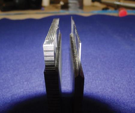
These two ribs were used to test the effectiveness of the 8:1 rule. Any deflection during milling of the thick rib could be assumed to be deflection of the tool alone. When the thin rib was milled at the 8:1 depth, total deflection was even less than what was seen with the thick rib—confirming the stability of the cut.
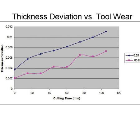
This chart compares the deflection for the two ribs seen in the previous photo.
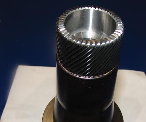
Compared to a 10- or 20-flute tool, the experimental 45-flute tool removes material even faster.
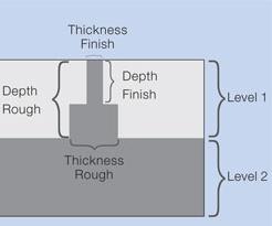
The application of the 8:1 rule not only proceeds in vertical stages, but also alternates between roughing and finishing passes. The numbers here indicate the order in which the regions of material would be removed to finish this rib. Areas roughed at a large axial depth are followed by finishing passes taken at lighter axial depths. The rib remains supported by the uncut material and emerges from the stock as the areas are removed in this sequence.
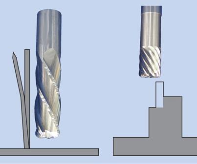
When pocket walls are milled in a single pass at full depth, cutting time is long and the thin wall is likely to vibrate. Machining in vertical steps using the 8:1 rule is a faster and more stable way to finish the pocket.
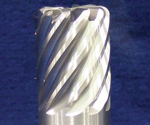
The 10-flute carbide end mill is a fundamental tool for achieving high metal removal rates when finishing titanium ribs.


Here is the most fundamental tool for milling titanium productively: an end mill with lots of flutes.
Researchers with the Boeing Research and Technology group (BR&T) in St. Louis explain that one of the most fundamental guides for determining how to apply such a tool is something the group calls the “8-to-1 rule.”
A tool with many flutes permits high metal removal rates during finishing. Titanium requires parts to be roughed and finished in separate steps. Aluminum aircraft parts are not like that. The speed and chip load at which aluminum can be milled permit high metal removal rates even when the tool is appropriate for finishing. But in titanium, the maximum practical cutting speed and chip load are much lower. Therefore, achieving a sufficient metal removal rate has to involve other strategies, such as taking a heavy depth of cut during roughing. During finishing, though—as a machined wall or rib becomes slender enough that cutting forces have to be reduced—a heavy depth of cut is no longer possible. What remains for productivity in finishing is to increase the feed rate. This can be done using a milling tool that has enough flutes to multiply the small chip load into a high value of inches per minute.
How many flutes? As many as you can use. Ten-flute end mills are available from various sources. A 1-inch-diameter, 10-flute tool running at 400 sfm and 0.003 inch per tooth produces a feed rate of 46 ipm. BR&T is routinely able to finish titanium at this speed and feed rate. The group also sometimes applies 20-flute end mills, and has experimented with a 45-flute tool (more on this below).
Again, these are tools for finishing. Their handicap is poor chip clearance resulting from the closely spaced flutes. To compensate, chip load generally has to be held to 0.003 inch per tooth, and the radial depth of cut for a 1-inch tool must not exceed 0.035 to 0.050 inch to leave ample room for chips to fall away.
As for the depth of cut in the axial direction, this is where the 8-to-1 rule comes in.
Because it defines the depth of cut according to how close the rib is to its final size, this rule essentially establishes the difference between roughing and finishing passes when milling pockets in titanium.
The Rule Defined
The 8-to-1 rule can be stated as follows: The maximum axial depth of cut should be no greater than 8 times the remaining thickness of a wall or rib adjacent to the cut.
For example, consider a pocket wall that must be machined to 0.050 inch thick. Roughing passes leave enough extra stock on the wall that it is still 1/8 inch thick after roughing. Because the wall is machined to this thickness, milling passes adjacent to it can be taken at a depth of up to 8 times this value, or 1 inch deep. (Boeing says 1 inch is also the maximum axial depth for the 400-sfm process cited above.)
Finishing passes along the wall then bring it to its final thickness of 0.050. These passes also can be no deeper than 8 times the machined thickness. In this case, this makes the maximum depth 0.40 inch.
Avoiding deflection is the reason for this ratio. Through experimentation, BR&T searched for a depth-of-cut guideline that could be applied uniformly across the range of wall and rib heights and thicknesses that Boeing components are likely to require. The photo of the two test specimens at right illustrates this experimentation. At 1/4 inch, the heavier of the two ribs is so thick that any deflection measured in the part could only have been the result of deflection of the tool. The sample thus provided a baseline for understanding the effect of tool deflection alone. In comparison, the 0.030-inch rib was machined using the 8-to-1 rule at an axial depth of 0.250 inch (call it 8.3-to-1). The deflection here could come from both the tool and part—but the graph shows the stability. For this rib, the overall deflection was actually less than the baseline deflection that could be expected from just the tool itself.
Titanium handles the 8:1 depth of cut because it is such a stiff material, say BR&T researchers. If the same rule were applied to aluminum, the ratio would be 4:1.
Finishing In Downward Steps
Limiting the depth of cut in this way means that deep pocket walls have to be finished with successive incremental passes. This is much different from the way pocket walls have typically been machined. Usually, the machining is done with a single finishing pass at the full depth of the pocket. This approach is sometimes seen to be not only more productive, but also conducive to a higher-quality pocket because it eliminates any feed lines between successive passes. Boeing believes both views are incorrect.
The single, full-depth pass generally requires a slow feed rate of 1 to 3 ipm. The corresponding metal removal rate is around 0.1 cubic inch per minute. By contrast, a 46-ipm pass in a series of 8-to-1 step-downs produces a metal removal rate of 2 cubic inches per minute. While this represents an increase of a factor of 20, it is only the beginning of the productivity improvement. An unsupported wall or rib typically vibrates during the full-depth pass, creating the need for repeated passes (“float” passes) to clean up the stock left uncut on the moving workpiece. For this reason, the vibration often results in poor thickness control, not to mention chatter marks that actually do have to be hand-blended away (unlike the generally harmless feed lines). The 8-to-1 process not only cuts the feature faster, but also avoids these additional steps.
But vibration is still a danger. To reduce vibration as the machined feature emerges from the stock, the successive passes should be taken from alternating sides of the wall or rib. Another illustration at right shows this. In fact, as the same illustration shows, the approach that maximizes support is to alternate between roughing and finishing all the way down. Completing the rib in this way means that the rib does not have to be touched again at each successive layer, as the tool descends to the next level of the pocket.
45 Flutes
To make the finishing passes even more productive, BR&T has been experimenting with how many flutes it is possible to cram into the cutter. The 45-flute tool shown is 2 inches in diameter. To allow the tool to be manufactured cost-effectively, it features a hollow core to reduce the amount of carbide required. At 400 sfm and 0.003 inch per tooth, this tool allows a feed rate greater than 100 ipm.
There are problems, though. The larger tool diameter increases runout error to the point of unacceptable variation in the chip load. The Boeing researchers are still experimenting with how to make this tool design practical enough to apply in production. For the time being, this tool represents the cutting edge—or 45 cutting edges—of how fast it is possible to finish-machine in titanium.
Editor’s note: You can read other parts in this series by clicking on Read Next (to the right).


Related Content

10 Things to Know About Creep-Feed Grinding
Because of the high material removal rate creep-feed grinding can deliver in challenging materials, grinding might not be just the last step in the process—it might be the process.
Read More
Best Practices: Machining Difficult Materials
Cutting hardened steel, titanium and other difficult materials requires picking the right tools, eliminating spindle runout and relying on best practices to achieve tight part tolerances.
Read More
The Strategic Value of Machine Tool Flexibility
This aerospace and defense supplier has a strategy to take advantage of the flexibility in its newest and largest five-axis gantry-type machining center.
Read More
SolidCAM Wants to Help Machine Shops Get into Additive Manufacturing
SolidCAM's partnership with Desktop Metal is aimed at making additive manufacturing more accessible to job shops and other manufacturers.
Read MoreRead Next

How To Machine Aircraft Titanium: Pricing The Process Instead Of The Tool
Part of a series of articles on more efficient machining of pockets in titanium parts, this article describes the importance of considering all of the costs that are affected by the choice of cutting tool.
Read More
How To Machine Aircraft Titanium: Getting The Metal Out
Part of a series of articles on machining pockets in titanium parts, this article describes various options for roughing the hard metal efficiently.
Read More
How To Machine Aircraft Titanium: Plunge And Sweep For Finishing Corners
Part of a series of articles on more efficient machining of pockets in titanium parts, this article describes an effective approach to finishing internal corners.
Read More