
Measuring Taper For Toolholders And Spindle Applications
Companies concerned about strict quality requirements regularly check toolholder tapers for wear or inaccuracy because these conditions can jeopardize the results of a critical operation. However, a shop can check tapers quickly and reliably with air gages. These devices can be used effectively without special operator training. For measuring taper in a production environment, few other methods can match the speed and performance of air, as multiple-circuit air jets can be placed in very small taper gages.


Companies concerned about strict quality requirements regularly check toolholder tapers for wear or inaccuracy. Production workers do not require special training to use air gages to conduct these checks.
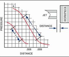
Fig.1—Restricting airflow creates a pressure-distance curve. This pressure-distance curve is rather linear over a portion of its range and is highly repeatable.
With a “clearance-style” air plug, the air plug is designed to fit the machine’s spindle with clearance between the plug and the spindle walls. At the same time, the air plug’s flange is referenced against the top surface of the spindle. This makes it possible to measure diameters at known heights.
The taper master is typically a more precise version of the part feature, such as the tapered portion of toolholders.
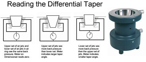
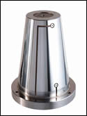
Fig. 2—Jam-fit tooling will detect a taper angle that is larger or smaller than it should be. However, this kind of tooling does not provide an indication of axial positioning accuracy. The taper air ring unit shown below is typical for jam-fit tooling.
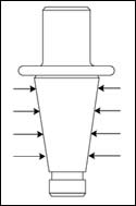
Fig. 3—An additional set of jets may be added to “clearance-style” air tooling to inspect for bell-mouthed and barrel-shaped errors in the taper.
Share


Phillips Corporation - Education
Featured Content
View More


Phillips Corporation
Featured Content
View More


The use of tapers has never been more important. Most toolholder designs use tapers because tapers provide good alignment and can be “locked” into position. In the manufacture of toolholders and spindles, the control of taper and size determines how well the machine can perform during its cutting cycle.
The two conditions most important in controlling taper are taper size and angle. Size is controlled by tolerance, and is, therefore, identical to a cylindrical ID or OD. Taper angle, on the other hand, can be controlled by at least three different factors: 1) included angle or angle per side; 2) taper per inch or per foot; 3) two diameters at specified datum locations.


Air gages effectively measure virtually all common types of dimensions and are particularly suited to checking such dimensional relationships. As an inspection tool, air gaging can measure many jobs more quickly, more conveniently and more accurately than other gaging methods. In the measurement of high precision hole conditions, for example, air gaging is unsurpassed for speed and accuracy. Also, when checking dimensional characteristics, air offers sufficient magnification and reliability to measure tolerances well beyond the scope of mechanical gages.
Also, air gaging is easy. Production workers do not require special training to use air gages. To check a hole, for instance, it is not necessary to develop skill in “rocking the gage” to find the true diameter: Merely insert the air plug in the hole, and read the meter. It is as simple as that.
How Air Gaging Works
Air gaging uses the principle of back pressure to determine the size of a measured part. According to the laws of physics, flow and pressure are directly proportional to clearance, and they react inversely to each other. Thus, the relationship between air pressure and the distance of a restriction (workpiece) to the air escape (jets) can be plotted on a graph. See line (a) as shown in Figure 1. As the distance between jets and work surface increases, the pressure decreases and the ratio becomes linear as represented by the straight section (b) in Figure 1. This straight portion of the curve can be accurately calibrated, and it represents the scale of the air gage.
For measuring taper in a production environment, few other methods can match the speed and performance of air, as multiple-circuit air jets can be placed in very small taper gages. Air taper gages are used throughout the process of machining, including:
- The inspection of new toolholders,
- the inspection of new spindles,
- the monitoring of used toolholders to ensure that they mate properly with the machine and
- the monitoring of the spindle to ensure that the toolholder is seating properly in the spindle.
Toolholders And Spindles
There are many types of standard toolholders, but the two most common are the CAT-V and the HSK. The NMTB and CAT-V are very similar and most frequently used. NMTB/CAT-V toolholders are external tapers, typically available in common sizes: 30, 40, 45, 50 and 60 (but others exist), depending on the size and capabilities of the CNC machine. Recently the HSK-style toolholder has also become popular for its high performance in high speed machining applications. Tooling sizes 32, 40, 50, 80 and 100 are commonly specified (but again other sizes exist). These numbers define both the gage line diameter and length. Both NMTB and CAT-V typically use a 7:24 taper while HSK uses a shallow 1:10 taper.
There are many reasons for the popularity of these toolholders. One advantage is that they are not self-locking, but instead, are secured in the spindle by the drawbar—an arrangement that makes tool changes simple and fast. They are also economical, because the taper itself is relatively easy to produce, requiring precision machining of only one dimension—the taper angle.
The toolholders must properly position the cutting tool relative to the spindle and, when secured in place, must rigidly maintain that relationship. The accuracy of the tapered surfaces on both the toolholder and the spindle is, therefore, critical.
If the toolholder’s rate of taper is too great, there will be excessive clearance between the two surfaces at the small end of the taper. If the rate of taper is too small, there will be excessive clearance at the large end. Either situation can reduce the rigidity of the connection and cause tool runout, which may show up on the workpiece as geometry and/or surface finish error. Taper errors may also affect the amount of clearance between the flange on the tooling and the face of the spindle, creating errors of axial positioning.
Three Types Of Air Tools
As the demands for precision machining and high speeds increase, manufacturing tolerances on spindle and toolholder tapers have gotten tighter. Nevertheless, both components are still subject to manufacturing inaccuracies and wear. In response, some companies with very high accuracy, quality and throughput requirements—particularly in the aerospace and medical fields as well as some automotive suppliers—regularly check the accuracy of toolholder tapers and the spindles of the machines using the toolholders. This is usually done with differential air gaging, which combines the necessary high resolution and accuracy with the speed, ease of use and ruggedness required on the shop floor. The most common type of air gage taper tooling has two pairs of jets on opposing air circuits and is designed for a “jam fit” between the part and the tool.
Jam-fit tooling does not measure part diameters, as such. Rather, it displays the diametrical difference at two points on the workpiece, as compared to the same two points on the master (see Figure 2). If the difference in diameter at the large end of the taper is greater than the difference in diameter at the small end, the upper jets will see more back pressure than the lower jets. This will reflect negative taper, or a larger taper angle. If the diameter difference at the small end is greater than the difference at the large end, the gage will read positive taper, or a smaller taper angle.
However, because a differential air meter displays diametrical differences only, it will not display the part’s diameter at either location. So, while this type of air tooling provides a good indication of taper wear and allows us to predict a loss of rigidity in the connection, it does not tell us anything about the tool’s axial positioning accuracy.
For that, we need a “clearance-style” air tool. The tool cavity is sized to accept the entire toolholder taper, while the toolholder’s flange is referenced against the top surface of the tool. This makes it possible to measure diameters at known heights (in addition to the change in clearance, as with the jam-fit type). An additional set of jets may be added, as shown in Figure 3, to inspect for bell-mouth and barrel-shape, two more conditions that reduce the contact area between the toolholder and the spindle.
There is a third type of air taper gage, which is a cross between the styles mentioned above. This is called a “simultaneous fit” taper gage. It is basically a jam-fit tool with an indicator that references on the face of the mating flange of the toolholder. This indicates how far the toolholder reaches into the spindle. So, while the air gage provides a reading of the taper angle, the indicator provides an indication of the size of the diameters. When measuring a tapered toolholder, if the taper diameter is too large, it will not go far enough into the gage. If the diameter is too small, it will drop further into the gage.
Given a basic understanding of how an air gage works, these types of tooling are easy to use. Mastering is simply a matter of inserting the taper master and adjusting the zero. Measuring is even easier: Just insert the part and take the reading. However, care is required, especially when handling heavy toolholders. Although air tooling is sturdy, it can be damaged.
Mastering Taper Gages
Air gages for taper tooling require taper masters. Toolholders are of particular interest, because the accuracy of the taper affects the quality of the parts manufactured with these toolholders. According to ANSI standard B5.10, V-flange toolholders are built with a specified rate of taper of 3 ½ inches per foot, +0.001/-0.000 inch. ISO standard 1947 defines a number of taper grades and establishes different tolerances depending upon both grade and taper length.
Regardless of which standard is followed, it is necessary to master the gage before it can be used to measure parts. The taper master is typically a more precise version of the part, but before it can be used to master the gage, it must be certified. ANSI’s 0.001-inch per foot tolerance seems easy enough to achieve until you look at the complexity of the inspection process. First, most toolholders are much shorter than 1 foot, so most gages actually compare diameters that are just 3 or 4 inches apart. Considering the 3-inch example, the part has to meet a gaged tolerance of 0.00025 inch (that is, 0.001 inch ÷ 4). Using a common 10:1 gaging rule of thumb ratio, the gage master should be accurate to 25 microinches, and the gage should resolve to the same amount.
To certify the master—again using the 10:1 ratio—will require a gaging system that has better performance then 2.5 microinches. This is easy to accomplish. A controlled laboratory environment is essential to achieve that level of accuracy. Certifying the master roughly replicates the production measurement process. The diameter of the master is measured at two known heights, and the slope or angle is calculated from the results.
Essential Considerations
The more you know more about your machining processes the better your tooling and spindles will likely perform. Air gaging can help fulfill that need. When specifying a taper requirement, always consider:
- What is to be measured:
-Taper angle?
-Diameters at certain locations?
-Taper and diameter? - The length of the taper and possible location for sensing points.
- If the gage should be portable or bench-mounted.
- What the operator needs for a readout.
- Simple jam-fit designs provide measurement of taper angle.
- The addition of an indicator provides indication of taper diameter.
- A shoulder-style gage allows for independent circuits for taper and diameter measurement.
- A third air circuit can help determine if the sides of a taper are straight.
About The Author: George Schuetz, Director, Precision Gages at Mahr Federal Inc., is a regular columnist in Modern Machine Shop.


Related Content

Choosing the Right Drill Type
Specifying the right option for your application can save time and tools.
Read More
Shoulder Milling Cuts Racing Part's Cycle Time By Over 50%
Pairing a shoulder mill with a five-axis machine has cut costs and cycle times for one of TTI Machine’s parts, enabling it to support a niche racing community.
Read More
Chuck Jaws Achieve 77% Weight Reduction Through 3D Printing
Alpha Precision Group (APG) has developed an innovative workholding design for faster spindle speeds through sinter-based additive manufacturing.
Read More
Eight Articles to Understand Live Tooling
A roundup of the most read articles about live tooling on Modern Machine Shop.
Read MoreRead Next

Modern Machine Shop’s 2026 Top Shops Benchmarking Survey Goes Live Feb. 1
Modern Machine Shop is proud to announce the 2026 Top Shops Benchmarking Survey, opening February 1 through March 31, 2026.
Read More