
Removing Metal Supports from Additively Manufactured Parts
What is the best way to remove metal support structures from AM parts?

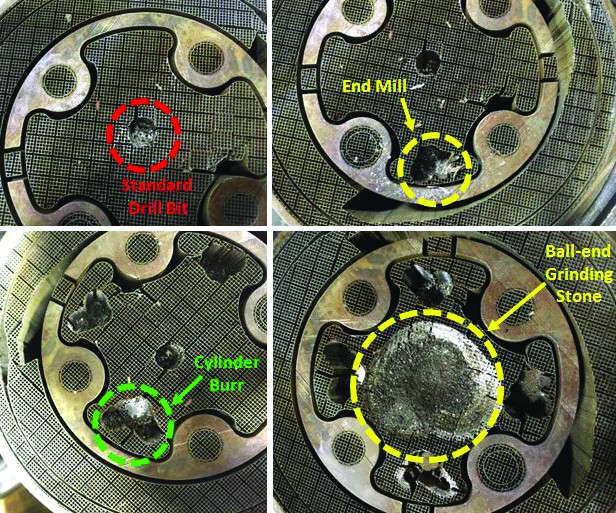
Fig. 1. These images show the results of attempts to remove stainless steel support structures from an AM part using different machine tools. (Photo courtesy of Logan Brown, Penn State University.)
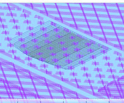
Fig. 2. This rendering shows the laser-scan pattern for a Ti64 part (gray) and its support structures (pink).
Share


Phillips Corporation
Featured Content
View More


Phillips Corporation - Education
Featured Content
View MoreAssuming you’ve already taken the necessary precautions that will allow you to safely handle parts additively built from metallic powder and feedstock, your next question likely is: What is the best method for removing their metal support structures? For parts manufactured in laser-based powder-bed systems, those support structures will be of the same material as the part itself, whether that is a titanium alloy such as Ti-6Al-4V (Ti64) or a nickel chromium alloy like Inconel 718.
Logic might dictate that you use the same feeds and speeds to machine away the support structures as you would to machine any other part made from these materials, but the jury is still out on this case for two important reasons:


1) In subtractive machining, you start with a material that has the properties you want and then create the shape you want from it. In additive manufacturing, it is the reverse: You build the shape you want and then heat treat, age and solution-anneal the material to get the properties you want. So depending on the postprocessing heat treatment (or lack thereof), the microstructure of an additive part will vary, which means you may not be post-machining the grade of material you think you are. In short, you will not know exactly what material you are machining when you are removing metal support structures from an AM part.
2) Support structures are often hollow, which means you are not continuously machining metal as you cut through them. The images in Figure 1 show what you will likely encounter: a thin-walled, mostly solid support, then air, then another thin wall, then air, and so on. Furthermore, most supports are not fully dense, particularly in the build direction. Since the supports will be removed from the finished part, it seems unnecessary to make them fully dense, so laser-path planning algorithms often skip every other layer of the supports, saving material and reducing build time. Figure 2 shows the hatch spacing (laser-scan path) for a part and its supports. The tightly spaced gray lines represent the laser path for the part, while the sparser pink lines indicate the laser path for the supports. The tighter hatch spacing yields a fully dense part, while the coarser spacing will lead to slightly porous supports.
Figure 1 also illustrates the challenges in removing internal support structures by different machining methods. These images were taken by a capstone engineering design team at Pennsylvania State University that was tasked with finding ways to remove the supports from a stainless steel piston crown. As you can see by the top left image, a standard drill was fairly ineffective, crushing the supports inward instead of removing them. The end mill (top right) and ball-end grinding stone (bottom right) were only slightly more effective, still tending to crush/tear the supports away versus cleanly removing them. As shown in the bottom left image, it was the cylinder burr that seems to have done the best job on this material and support-structure geometry, removing the supports cleanly as it plunged into the stainless steel thin-walled structures. Had the part been heat treated or made from a different material, or had a different support geometry been used, the results likely would not have been the same, and a different tool/approach would likely have faired better.
In summary, machining away metallic supports remains a challenge for additive manufacturing. While most researchers have focused on gaining a better understanding of the additive manufacturing process itself, few have spent the necessary time and energy to understand what it takes to remove support structures and finish additively manufactured parts efficiently and effectively. In many cases, service bureaus offering AM capabilities do not have postprocessing and finishing capabilities in house or may not be asked (or inclined) to remove support structures from a part. For those of you that have both additive and subtractive capabilities, or an interest in contributing to the postprocessing of additively manufactured parts, we desperately need your help.


Read Next

Modern Machine Shop’s 2026 Top Shops Benchmarking Survey Goes Live Feb. 1
Modern Machine Shop is proud to announce the 2026 Top Shops Benchmarking Survey, opening February 1 through March 31, 2026.
Read More