
Absolute Control
Tool management for this aerospace manufacturer begins in NC programming and reaches throughout the shop floor.


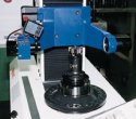
The Zoller presetter is the final check that tools are assembled to spec, and where fine offset measurements are made. Once it is fully integrated, off-set values will flow directly to machine tool controls.
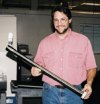
John Dom displays one of Dowty's key manufacturing capabilities, precision deep boring.

Dowty's core business is making hydraulic actuators for flight control systems.
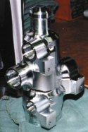
When this DCV valve was moved to a five-axis machine, the six setups previously required were cut to two.

The Zoller presetter is the final check that tools are assembled to spec, and where fine offset measurements are made. Once it is fully integrated, off-set values will flow directly to machine tool controls.

Dave Knapik manages the NC programming department and has overseen the implementation of the tool management system.
In most shops, conventional wisdom has it that the creation of NC programs is within the domain of a CAD/CAM department and that management of cutting tools is something best left to the shop floor. Who knows better what tool is best for a job than the people who cut every day? Perhaps more to the point, who knows what's available in the crib when it comes time for a setup? So most shops are content to create an NC program in a highly theoretical environment, and then let setup people dial it in with offsets and the feed rate override on the shop floor.
It's mainly a concession to practicality. CAD/CAM systems are great at creating the mathematical geometry of a workpiece, and fitting a tool path to it. Many are adept at maintaining large repositories of cutting data. But in practice, that cutting data is usually basic in nature—a conservative starting point intended to be modified on the machine. It's similar with the choice of cutting tools. The NC programmer often picks generic tools from a menu. While tool diameter is usually right, actual tool length is a guess. That necessitates a program "fitting" process on the shop floor where the dimensions of theoretical tools are replaced by the real thing.


To be fair, today's program verification technology helps. CAM systems have gotten pretty good at preventing a programmed tool from gouging the workpiece. But that won't save you if the actual tool turns out to be longer than the simulated model. Fixtures and clamps are an issue too, since few shops verify part programs within the context of a real setup, and toolholder interference is rarely checked at all. Moreover, available data to modify feeds and speeds for different tool lengths or extensions is often spotty at best, and ultimately irrelevant if the NC programmer doesn't really know what tool is going to be used anyway.
But what if it was different? What if NC programmers had all the process information they needed to fully plan and execute a job? What if they knew exactly what tools were available and could ensure that the tools they specified would be used, no exceptions? What if they knew the exact dimensions of not only the workpiece, but of the cutting tool assemblies and workholding too? If so, couldn't the whole process be simulated off-line? Couldn't jobs run well with the very first part? Couldn't setups be completed quicker? Wouldn't quality improve by taking so much variability out of the process?
That's exactly where Dowty Aerospace Los Angeles (Duarte, California) is headed. This company has a no-offset policy in all their CNC machining operations—meaning that all tooling is specified, modeled and verified in the NC program, and then that real tool kits are prepared that conform exactly to the program. How Dowty is building its tool management system has everything to do with their ability to make it work.
No Surprises
While you may not have heard of Dowty Aerospace, if you've spent much time on airplanes, you've surely come to appreciate their work. Dowty makes hydraulic actuation systems that are used in such applications as thrust reversers that provide controlled deceleration upon landing, landing gear extension and retraction systems, landing gear and cargo doors, rudder controls and other flight control systems. Dowty's equipment is used widely in commercial aircraft, including Boeing 737, 747, 757 and 777 jets and Saab 2000 turboprops, as well as military F-5, F-15 and F-18 fighters. At one time the company was owned by Boeing, but it is now a unit of the British conglomerate TI Group PLC. The Los Angeles facility currently produces about $90 million worth of output with some 270 employees.
Given the critical performance requirements of Dowty's products, the company can ill afford to leave anything to chance on the shop floor. So they strive to maintain as much control as possible over the total manufacturing process, from design through to final assembly. That control certainly applies to cutting tools, both from the standpoint of strictly managing all cutting tool data and of managing physical inventory as well.
It's not a discipline that is new to Dowty—indeed, they've been doing it for years. What the company has done recently, however, is apply new "tools" for managing their tools. For instance, they've installed graphical tool management software that helps bridge the information gaps between NC programming, the tool crib and the machine setup process. This software allows NC programmers to quickly search for existing available tool inventories, to associate cutting data with those tools, and to communicate to the crib and machinist in an easy-to-understand manner exactly how the job was programmed and how the tool kits should be set up. Moreover, they're adding networked tool presetting equipment that is streamlining the tool setting process, and they are making sure that these new assets integrate suitably with existing management systems. Combined, the systems provide company-wide access to critical tooling data—data that is used for both planning functions and execution on the shop floor.
Building Blocks
The new tool management software is the BravoTDM system from Applicon, Inc. (Ann Arbor, Michigan). At the heart of the system is an Oracle relational database that allows cutting tools to be managed, not as single entities, but as fully associative assemblies. That is, the individual components of a tool assembly—toolholders, bodies and inserts, for instance—can be related to one another based on the mating physical interfaces, and the whole assembly can be related to cutting data for that type of tool. It is, in essence, a bill of materials, CAD assembly model and cutting data handbook all rolled into one.
The three-tier structure of the database facilitates a building-block approach to specifying tooling that can substantially reduce time and/or the guesswork in planning a job. At the first level is the component record. Here, the individual pieces of tooling are described with all the necessary information for that type of component. On a face mill body, for instance, that would include an ID number, description, number of teeth, maximum depth of cut, physical dimensions, weight and so on. The tool is also associated with a general tool class (face/shoulder mills) and sub-group (face mill) that will become important when searching for available tools. Moreover, mating interfaces of each component can be classified so that searches can be confined only to components that fit together. For example, once a cutter is selected, it becomes possible to conduct a search only for toolholders that fit the back end of the cutter and only for inserts that fit the front. And, importantly, all the data is linked to a CAD file of the component. Recommended cutting data is typically attached to appropriate tool component records as well.
At the second level is the assembly record, where all the components necessary to build a machine-ready tool are gathered. A fully dimensioned assembly drawing is provided, which can be automatically pulled from the individual component files if the system has the necessary CAD links in place. As at the component level, the drawing does not actually reside in the tool management system. Rather, it is pulled from the CAD system database whenever a record is activated.
Critical process data, such as feed and speed recommendations, that were associated with a component are automatically brought forward into the assembly record. For the cases where baseline cutting data aren't appropriate for all circumstances, the system has the capability to store multiple sets of cutting data. For example, aggressive feeds and speeds may be appropriate for a standard cutter-and-toolholder combination, but something more conservative will be necessary if an extension is involved. Cutting parameters for different materials must be accommodated as well. As such, the system allows as many sets of cutting data as required to be associated with a tool, which can be alternatively applied at the NC programmer's discretion.
At the third level of the system is the tool list in which all tool assemblies required for a job can be grouped. The system has the ability to compare one tool list to another in a variety of ways. One application of that capability is to compare the tool assemblies required for a new job to tools currently resident on the machine so that only the necessary new tools will be kitted for setup.
The system also has the capability to manage physical tool inventory in the shop. That means tracking tools from crib to machine and back, reporting on usage, maintaining sufficient quantities on hand, generating new order requisitions and so on.
First, The Hard Way
The reason this functionality is so useful to Dowty is that it fits almost perfectly the disciplines they've applied to tool management for years. The software only makes them more efficient. According to NC programming department manager David Knapik, Dowty has had systems in place for five years or more to manage tooling data and inventory, and had developed their own group technology (GT) coding system to help deal with tool assemblies. But these were largely standalone applications and thus not well integrated with one another. Moreover, tooling documentation was not graphical in nature, and thus not as easy to understand on the shop floor as they thought it should be.
Mr. Knapik wrote the initial tool data management application himself, which he describes as an "electronic Rolodex" with a "card" for each tool assembly used in the shop. Each card was essentially a bill of materials for the assembly. It was a little crude, but it was an enormously useful step in building the discipline to use the same tooling information in job planning and execution. The GT coding system allowed virtually any tool to be described through a standardized nomenclature. For example, EM.25F4R.03-2212 might look like a meaningless part number to the uninitiated, but to the trained Dowty NC programmer and crib attendant it quite obviously is part of the end mill family (EM), ¼ inch in diameter (.25), four-flute (F4) with an edge radius of 0.03 inch (R.03). The last four digits indicate the tool material (cobalt), flute length (standard), flute type (general purpose) and type of end mill (square end).
So, the identification code carried most of the information necessary to build a tool assembly. Along with that information, the tool card included the type of toolholder, the set length, manufacturing part number and basic vendor information. Preparing tooling documentation for a repeat job, then, only required "pulling" all the required cards and providing that information to the crib where the tooling would be kitted for the impending setup. For new jobs, the GT coding—which was also used in the separate physical inventory system—made it possible to search a database for available stocked tooling options. What the tool cards didn't do, however, was present an intuitively obvious picture of job requirements to the person assembling the tools. Correctly interpreting non-graphic data took careful concentration on the part of the crib person, making his job more difficult and raising the likelihood of mistakes.
Technology Applied
With the new system, applying Dowty's tooling disciplines is easier and more efficient across the board. According to NC programmer John Dom, to create a new tool assembly, all they have to do is pick components from the database, typically moving from the cutter back to the machine interface. He demonstrates with an example of how it works as he explains. He first goes to a master screen that groups all cutters by type, picks a category, selects the correct size, and the component data is immediately imported into the new assembly record. Now, if he wants, he could simply click on a graphic of the tool shank to bring up a list of available toolholders
that fit the cutter. But since he knows Dowty's GT coding system by heart, he'll go directly to a list of options that he can recognize just by number, and for fun he'll put the tool on an extension. He picks a collet, then an extension, then another collet, then finally the toolholder and retention knob that fit the machining center. As he does this, each component is automatically being added to the assembly record. Then, with a single click of the mouse, he instructs the system to generate the tooling documentation. The system pulls each component model from the CAD system and generates a completely dimensioned assembly drawing automatically. The whole process literally takes less than a minute.
Dowty likes to standardize wherever possible, however, so the first choice is to find an existing assembly if it's appropriate. About 60 of the shop's most frequently used tool assemblies never get torn down, so if they can use one of those, it's more efficient overall. But whether they can or not, having detailed tooling information in a database makes it much easier and quicker to search for whatever options are available.
Mr. Dom believes that this efficiency makes a huge difference in a busy programming department. Besides the fact that he and just one other programmer, David McKay, support 48 CNC machines, the department is responsible for much of the machining process planning and shopfloor documentation. "Eighty percent of the work has something to do with tooling," he says, and having a better means to work with that data is a welcomed asset.
But the advantages extend way beyond the tool planning process, and it is here that Dowty is poised to reap further gains. For one thing, the tool management software integrates directly into Dowty's Bravo CAM system, which is also provided by Applicon. So when Mr. Dom and Mr. McKay are creating new part programs, they can pull all that data forward into CAM, instantly knowing what tool configurations are available and exactly what the physical dimensions of the real tool assemblies will be. That allows them to program and verify routines in a virtual environment that is fully representative of the real machining environment. As a final check, they model the entire setup—including tool path, cutting tools, toolholders and workholding—and verify the process in Vericut (CGTech, Irvine, California), another system for simulating NC programs. It's an extra step that takes a little time, but one that has virtually eliminated crashes as well as the time used verify new programs on the machine.
Also critically important, the programmers can pull the tool list from the routine and send complete documentation to the crib with but a few more clicks of a mouse. During our visit, Dowty was in the process of integrating the control of a new tool presetter from Zoller (Ann Arbor, Michigan) with the TDM software for a completely paperless process. (That work should be complete by the time you read this.)
Paper or not, it is the crib's responsibility to assemble tools exactly as they are specified in the documentation. Tolerances and wear in the tooling itself are going to necessitate the use of some machine offsets, of course. But out of the crib, they will accept no offset value greater than 0.010 inch.
One aspect of Dowty's tool management system they haven't yet integrated is the physical inventory system. It's not that the advantages of having all tooling data reside in a single database are lost on Mr. Knapik and his staff, but they have so much time invested in developing the inventory system they already have that they can't yet justify the conversion.
For now, they prefer to concentrate on flushing out the new systems they are putting in place. Not all tool data have yet been entered for existing work in the shop. For the first couple months they elected to move carefully into the new technology, taking it on a job-by-job basis, just to make sure all the fine points are worked out. Mr. Knapik intends to launch a concerted effort soon to fully document all tooling for the shop's 50 most common part numbers.
That initiative will go along with a continuing effort to improve processes. Dowty has moved a number of parts to more capable machines, including a five-axis high speed machining center, which is reducing both setups and cycle times. That's taking some experimentation and a lot of collaboration between programmers and machinists. But once they've arrived at a good process, they now have the ability to "lock it down" with excellent total process documentation and procedures. Tooling is no longer a major variable under this discipline, and that frees everyone to concentrate on the next increment of improvement.


Related Content

Twin Spindle Design Doubles Production of Small Parts
After experiencing process stalls in the finishing stage of production, Bryan Machine Service designed an air-powered twin spindle and indexable rotating base to effectively double its production of small parts.
Read More
New Modular Tool Options for Small Spindle Milling
Tooling options have been limited for small spindle milling applications. Now modular, indexable systems are available that provide broad flexibility to get the right cutter for the job with less inventory and at lower cost.
Read More
Selecting a Thread Mill That Matches Your Needs
Threading tools with the flexibility to thread a broad variety of holes provide the agility many shops need to stay competitive. They may be the only solution for many difficult materials.
Read More
Buying a Lathe: The Basics
Lathes represent some of the oldest machining technology, but it’s still helpful to remember the basics when considering the purchase of a new turning machine.
Read MoreRead Next


3 Mistakes That Cause CNC Programs to Fail
Despite enhancements to manufacturing technology, there are still issues today that can cause programs to fail. These failures can cause lost time, scrapped parts, damaged machines and even injured operators.
Read More
The Cut Scene: The Finer Details of Large-Format Machining
Small details and features can have an outsized impact on large parts, such as Barbco’s collapsible utility drill head.
Read More