
Stepping Into Solids Machining
Moving from pure surfacing to hybrid solid-and-surface modeling was much easier than this pattern shop ever thought it would be.


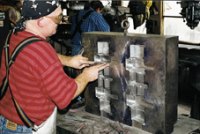
Like many tooling shops, Industrial mixes high levels of technical and hand skills.
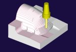
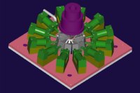
Industrial designed this 12-slide tool to make sand cores for an oil skimming impeller. The photo shows the front of the tool, and the model shows the slides.

Barry Bundesman was already skilled at surfacing, but he was just learning solids for the first time.
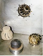
Not all of Industrial's machining is in metal. This pattern is for a truck vent.
It wasn't that Barry Bundesman was dissatisfied with surfacing. Quite the contrary, he had a top-notch CAD/CAM system, was really good at using it, and he could model any job just about any way he pleased. But the two-man CAD/CAM department at Industrial Pattern (Benton Harbor, Michigan) was at a crossroads. Barry was on a high-power UNIX system, his partner Mike Anstey was on a more modestly appointed PC-based system, and the inability to share native files was getting cumbersome. Flexibility is paramount in a small shop. They needed to easily pass work back and forth, so one could finish what the other started and to work on jobs together. It was time for them both to be using the same software.
Barry's first choice was just to get another seat of the system he was using. When you've devoted years to mastering a complex CAD/CAM system, scrapping all that knowledge for something new isn't the most appealing option. But there were financial issues to consider. The software and the workstation to run it on would push the tab over $50,000. And there were questions about the technology. Some of Industrial's customers were already moving on to solid modeling, and beginning to think that their suppliers should too. Solid modeling did seem to be an awfully efficient way to build a lot of geometry, and the systems now were getting pretty inexpensive and easy to use. No doubt, solid modeling was somewhere in this shop's future; the only question was when.


In the final analysis, shop owner and president Steve O'Connell decided sooner was better than later, and purchased two new seats of a solids-based CAD/CAM system. While the two programmers fully admit they are still learning solid modeling, they are learning fast. Here's how it's gone so far.
Building Speed
Industrial Pattern is a study in contrasts. Walk in the front door and you find a woodworking shop that hand-fashions patterns in the finest time-honored tradition. Walk in the side door and you find a modern CNC shop. Both the craftsman and the CNC technology have a rightful place in today's toolmaking environment, Mr. O'Connell believes, but no one disputes that the biggest part of their future lies on the CNC side of the business. Either way, Industrial's primary business is in making foundry patterns, though they also produce about a dozen blow molds a year. The shop stakes its reputation on high quality, good technology, and its ability to respond quickly to customer needs.
CAD/CAM lies at the center of all these attributes, both in terms of image and performance. "Obviously it's one of those things you have to do," says Mr. O'Connell. "Have it or you're not going to get to play." But that's only half the formula. Once you're in the ballgame, you still have to know how to play well, and that raised the two critical issues in the shop's choice of a new CAD/CAM system. First was the capabilities of the system itself and second, but no less important, was just how quickly Industrial's programmers could learn to use it to good effect.
According to Mr. O'Connell, speed is the primary driver in the pattern-making business—that is, the ability to move quickly from sometimes sketchy customer data to produce a high quality tool. So the speed by which jobs are modeled and tool paths produced in CAD/CAM has everything to do with how successful the shop can be. And that factor as much as anything is why the move to solid modeling makes so much sense. "Solids let you do many things faster," says Mr. O'Connell, and speed is what they do best.
Hybrid Modeling
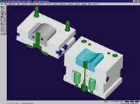
That's not to say that solid modeling does everything better, particularly with the flowing 3D geometry that is the stock and trade of the tooling business. This is why Industrial chose a "hybrid" modeling system—that is, one that allows Industrial's programmers to work with both surfaces and solids within a single environment. The software they chose is the VISI-CAD and VISI-CAM system with the Solid Manufacturing package from Vero International (East Hartford, Connecticut).
The industry need for hybrid modeling became apparent several years back as solid modeling technology, which had made huge inroads in product design, started to move downstream into tooling design functions. The great advantages of solid modeling are that it allows a complex volume of material to be represented and manipulated as a single entity, and that it allows two such entities to be added to or subtracted from one another. Take a simple cube, for example. As a solid, it is a single "airtight" object, meaning that its entire surface area is defined with no "holes" in the skin. Though the shape is mathematically defined by its outer boundaries, much like surfaces, those areas must by definition be completely joined, and so the system "knows" which side of the skin is in and which is out.
Now contrast the solid with a surface model of the same shape, which at the very least will be constructed of the six separate surfaces that make up the faces of the cube. If the edges each have a radius, that will require an additional eight surfaces along the edges and eight more at the corners, for a total of 22. With the solid, when the radii are applied, the corner volumes are subtracted from the original, and the model remains a single airtight entity.
Now drill a hole through the center of the cube. With surfaces, the cylinder surface is constructed and joined to the intersecting outer wall surfaces, which then have to be trimmed to the hole diameter. With the solid, the cylinder volume is simply subtracted from the cube volume. Now change the depth of the part. With surfacing, nine entities may have to be edited—four walls, four fillets, and the cylinder. With the solid, all the user changes is a single dimension.
While surfacing systems today have many features to automate such simple functions as those mentioned here, they nonetheless require a great deal of tedious interaction with the user, particularly when there is a lot of filleting and trimming to be done. On balance, building 3D geometry with solids is considerably more expeditious than with surfacing, and in a large sense more failsafe because there are by definition no gaps in the model that could turn into trouble when it comes time to generate tool paths. For the toolmaker, the ability to add and subtract volumes grows increasingly appealing as you think about transferring 3D part geometry to cores and cavities. Though grossly oversimplified, it is not too far off base to say that a mold maker can take a solid part model, apply a shrink factor, and then simply subtract the appropriate portion of that model from each half of the mold.
But there's a big catch. While solid modeling is great at manipulating 3D geometry once you have it, it may not be the best tool for creating a lot of that geometry in the first place. Says Mr. Bundesman, "It's (solid modeling) way faster than modeling with surfaces overall, but there are still a lot of things you can do only with surfaces." In general, surfacing is still better at generating the asymmetrical forms common in toolmaking, and in particular, the forms that are derived from sections and drive curves as well as the blends that join one irregular surface form to another. To create this kind of geometry, you need surfaces. Moreover, many of Industrial's customers work with surfacing CAD systems themselves, and thus can provide only surfaces workpiece files. It takes a surfacing system to translate those files and, invariably, to repair them once they've been imported into Industrial's system.
The hybrid modeling system lets Industrial have the best of both worlds with the ability to use both solids and surfaces in a single model. It is this ability to still use surfaces where surfaces work best that allows this shop to reap the kinds of benefits that solid modeling brings everywhere else.
In Practice
Both Mr. Bundesman and Mr. Anstey believe that solid modeling not only is faster, it's easier too, at least by today's standards. While Mr. Bundesman had come out of a toolmaker's apprentice program and had years of experience with eight different CAD/CAM systems, Mr. Anstey was just a year off of the woodworking bench. Still, they were up and running in a couple of days with nothing in the way of formal training. That's certainly not to say they were expert, but they were doing surprisingly complicated work within the first week.
Having the ability to work with both surfaces and solids was, and continues to be, important to achieving quick returns on the time invested. It allows the programmers to use the best tool for the job and circumstance at hand. More specifically, the modeler allows a variety of ways to construct geometry. The solid modeler includes the basic construction tools one would expect to find in a wireframe modeler (though the true model is still a solid), plus more advanced features including the ability to model parametrically in which any workpiece feature can be defined in relation to other features. This capability allows great freedom in editing a model without disturbing critical functional relationships between features. A simple example was our cubic workpiece with the through-hole. Shrinking the workpiece thickness brought the entire top topology of the workpiece down to the proper level, rather than having to deal with the individual entities from which that topology was created. Likewise, the depth could have been increased without having to individually "stretch" the through-hole cylinder or any other feature for that matter.
The creation of surfaces is handled in a fashion similar to conventional surfacing systems, but with one critical difference. Surfaces can be built right on top of the solid model, and then merged into the solid, or not, depending on the requirement. If the entire model is solid, the programmers can then immediately begin creating tool paths without first having to convert the solid back to surfaces as earlier generations of so-called solids machining technology required.
If there are surfaces in the model, they also can be machined directly. Surfaces can be machined individually when desired. Or, all surfaces can be machined as a single entity along with any solid components by converting the geometry to an STL format tessellated model, as many surfacing-only systems today do. That is, the surface or hybrid model is "shrink-wrapped" with an airtight mesh of triangular facets, the size of which are determined by a user-specified tolerance to the underlying reference geometry.
According to Mr. Bundesman, Industrial uses all these techniques to one degree or another, depending on the circumstance. He says, "If you are doing 100 percent of the modeling and tool path generation, creating a complete solid model is best. But if you are getting a surface file from a customer, then you have little choice but to work in surfaces, and converting it to a solid may not be worth the work. With solid systems you have to make the model airtight, and if you just want to quickly make some tool paths, it's just not necessary to model everything to the nth degree."
There are significant exceptions to that latter view, however. Perhaps the best example is the case where they know that a part model will be around for a while, and that it is likely to go through a number of engineering revisions over the course of its life. "It's far better to have a solid model down the road when the changes come," says Mr. Bundesman. A good case in point is the tool for making sand cores shown on page 58. The brass casting is an impeller used in oil field skimming systems. Because the pitch of the blades is critical to system performance, Industrial has already seen several iterations of the impeller design, which of course impacts the design of the 12-slide tool. Since still more modifications are likely to come, Mr. Bundesman felt it was well worth the effort to completely solid model this tool even though he had already originally modeled the job in surfaces.
Another good reason to work with solid modeling is when the workpiece requires a lot of filleting and trimming, at which solid modelers are particularly adept. "That's a lot of work with surfaces," he says, "but unbelievably easy with solids."
Still another reason to completely model a job—whether it is in solids or surfaces—is for the process verification benefits it provides. Industrial's CAM system generates a high-definition, pre-post simulation of the cutting process that reveals not just the movement of the tool, but also the state of the material left behind. That information is critical to determining if the part program is correct before it gets to the shop, a particularly important factor with Industrial's machining methods. Says Mr. Bundesman, "A brake caliper might come in here with 3,000 surfaces. On a job like that, it's much better to model it all up and then simulate the process. When you model, you know what the part looks like, but when you machine (in CAM) it's easy to miss small areas. Ninety percent of our machining is done unattended. Without simulation I would come in thinking a part was completely machined only to find out that not all the material had been removed." And so Industrial simulates every cutter path, both before and after post processing.
There are still other advantages to integrating CAM with a hybrid modeler. A big one is being able to do all their work in a single environment. Before, it was not uncommon for Industrial to begin modeling a job in the PC-based surfacing system, finish modeling in the UNIX system, then import the geometry into Autocad to create part prints, and still do the 2D programming in the shop because the surfacing systems weren't all that good at it. Now all that work can be done within a single database, eliminating the need for all those file translations. That saves a lot of time on the front end, but even more later on when engineering revisions are added to the model and drawings and tool paths are regenerated with minimal operator input.
Eye On The Future
While it would be nice to say that Industrial has incorporated all these possibilities into their daily operations, the truth is that they are still learning how to make the most of solid machining technology. As much as they like what they have accomplished so far, what they really covet is where the technology is leading them. For example, the newest version of the software includes a "history tree" that provides a new way to get an easy-to-use handle on the entire modeling-through-programming chain. Much like the history function now being built into Internet web browsers, the history tree keeps a running log of each step of the modeling and programming process, allowing the user to retrace his steps leading up to any point in the process. That will be a handy tool for editing parametric models where many features are defined by their relationships to other features and for selectively editing or re-sequencing tool paths.
Even more promising is the increasing amount of application intelligence being built into solid modeling systems. Vero International already has an intelligent mold design package that automates the creation of many standard mold attributes (see box), automatically imparting appropriately sized hole features to bases and blocks for such components as leader pins, ejector pins and bolts, and associating those features with the purchased components in assembly diagrams. It is only a small leap to go ahead and associate those hole features with the machining processes to create them—development work that is currently underway.
The people at Industrial Pattern know that kind of capability lies somewhere in their future. The capital and learning investments they are making in solid machining today will get them there faster.
For more information from Vero International on Solid Manufacturing, call (860) 282-2111 or visit Vero's Showroom.


Read Next

The Cut Scene: The Finer Details of Large-Format Machining
Small details and features can have an outsized impact on large parts, such as Barbco’s collapsible utility drill head.
Read More

3 Mistakes That Cause CNC Programs to Fail
Despite enhancements to manufacturing technology, there are still issues today that can cause programs to fail. These failures can cause lost time, scrapped parts, damaged machines and even injured operators.
Read More