Turn-Mills 101
Turn-mills are a type of multitasking machine that can shorten cycle times and help facilitate lights-out machining for two common machining types.

Share


Phillips Corporation
Featured Content
View More
Phillips Corporation - Education
Featured Content
View More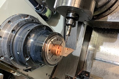
Live-tool CNC lathes may not match the flexibility of full turn-mills, but they can still machine parts impossible for traditional lathes. In this case, Chick Machine Company used the lathe to machine a square part.
Turn-mill machines are a type of multi-tasking machine capable of both rotating-workpiece operations (such as turning) and rotating-tool operations (such as milling and drilling). They enable users to machine workpieces complete on a single piece of equipment—increasing accuracy by reducing setups and positioning adjustments, decreasing footprint compared to dedicated machines for each operation and reducing backlog waiting for different machines to become available on the shop floor.
Adoption of these machines increased heavily during the 2010s, a change that Modern Machine Shop’s Peter Zelinski credits to two developments. First, CAM software and postprocessors have caught up with these machines and can now reliably run them. Second, more shops have become interested in them as a means of facilitating automation.


Over the past decade, programming and control software advancements have gone beyond basic compatibility for turn-mills. Some systems use AI and machine learning in conjunction with digital twins, optimizing tool paths on offline testing grounds to reduce cycle times and eliminate potential crashes. Ongoing efforts to develop powerful postprocessors that limit the need for G-code editing should also lower the programming entry barrier for turn-mills.
As for shops becoming more interested in using turn-mills for automation, surveys from Gardner Intelligence’s Top Shops program show that the best predictor of whether a shop is likely to conduct light-out machining is whether that shop uses a turn-mill machine — followed by whether it uses a Swiss-type lathe, twin-spindle turning machine or twin-turret turning machine.
Lathe or Mill?
Many turn-mill machines are based on lathe designs, with the milling spindle more supplementary. This setup evolved from live-tool lathes, which use driven spindles that mount on a tool gang plate or turret to mill flats and drill holes.
The best predictor of whether a shop is likely to conduct light-out machining is whether that shop uses a turn-mill machine.
Another common form of turn-mill, B-axis turn-mills, more closely resembles a mill, but offers both five-axis milling and turning functionality. The turn-mill’s rotating milling head can machine parts held in the spindle or subspindle from many different angles. These parts don’t need to be the round parts of turning, either, with the B-axis flexibility enabling processing of fully prismatic parts or machine-contoured parts.
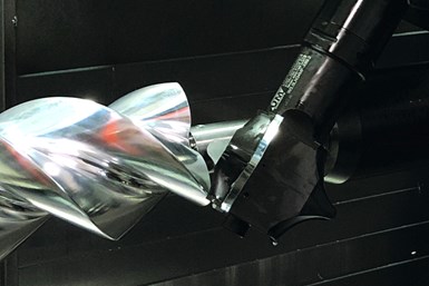
B-axis milling spindles open the door for a wide variety of machining operations, including complex contouring operations for turned parts.
These B-axis turn-mill platforms can perform simultaneous milling and drilling operations, as well as more complicated maneuvers such as pinch turning, skiving, contoured turning work and “turning milling,” where instead of feeding a static, single-point turning tool down the Z-axis, a spinning milling tool is moved down the part to “turn” the diameter. These machines are also good at creating big, shaft-like components that need milled features, such as large crankshafts.
More traditional twin-spindle and dual-turret turn-mill configurations can also improve performance, but may require synchronization of separate part programs running simultaneously, lest workpieces or spindles collide. Swiss-type machines with B-axis milling spindles have also become larger players in the turn-mill field, especially after the debut of automatic toolchangers and full-power B-axis spindles expanded their audience from shops working with small-diameter barstock to shops working with larger parts.
Tips and Tricks
Turn-mill users should follow a few workholding and parts loading best practices to optimize productivity.
When using a subspindle in conjunction with a bar feeder, the subspindle grabs the end of the bar and pulls out the length needed for the next part. As the subspindle will be more precise in pulling out the stock than the bar feeder is at pushing the stock in, relying on the subspindle for positioning will improve the final results for high-tolerance parts. Also, once the parting tool severs the finished part from the barstock, have a parts catcher ready so the turn-mill’s subspindle can drop the workpiece and make room for the next part.
If using automatic subspindle transfer, use three-jaw or dead-length collet chucks. If a collet or chuck moves in or out slightly, pushing or pulling on the workpiece when clamping, this unwanted motion could easily mar the workpiece.

_ROS-Display_Made-For-This-300x250_Final.jpg;maxWidth=300;quality=90;format=webp)


Related Content

Why Slow Quoting Is Costing U.S. Machine Shops Work
A shop can have the right machines, people and capacity — and still lose the job. The reason may be quoting speed. This AI tool is built to close that gap.
Read More
Shop Tour Video: How to Integrate Additive and Subtractive Machining
Addman Advanced Metals has scaled from a single 3D printer to 25 while also building out a robust array of subtractive machines. In this video, find out how the shop manages its additive and subtractive workflows — and how it combines the two into a profitable niche.
Read More
Understanding the Tribology of the Tool-Workpiece Interface
Machining is fundamentally a competition between the cutting edge and the workpiece material as it is sheared away to obtain the desired part geometry.
Read More
2 Secondary Coordinate Systems You Should Know
Coordinate systems tell a CNC machine where to position the cutting tool during the program’s execution for any purpose that requires the cutting tool to move.
Read MoreRead Next

WEBINAR: From Machine Data to Guided Action: How Modern Shops Are Closing the Execution Gap
In this webinar, MachineMetrics Product Manager Josh Fish is joined by Pindel Global Precision's Thomas Deslongchamps, for a candid look at what closing the execution gap actually looks like inside a precision machining shop.
Read More

