5 Ways the External Work Offset Can Help You
External work offsets can be valuable because they let you shift the point of reference for fixture offset entries from the machine’s home position to a more logical one.
.jpg;width=70;height=70;mode=crop;format=webp)
Share


Phillips Corporation - Education
Featured Content
View MorePhillips Corporation
Featured Content
View More


All CNC machining centers have some form of work coordinate system setting, commonly called fixture offsets, which are used to specify the location of program origin/s. The programmer chooses each origin, the position from which program coordinates are specified, based on how the workpiece is located during setup. Selecting logical program origin/s makes it easy for the programmer to determine programmed coordinates and the setup person to assign program zero during setup.
In normal use, each fixture offset is used to specify the distance and direction in each axis from the machine’s home position to the program origin. This often involves time-consuming measurements using a spindle probe, dial indicator or edge finder. If the workholding device for a repeated job is qualified, these measurements need be taken only once. If not, the measurements must be repeated every time the job is run.


Since the method just described is so popular, you may not know there could be a better alternative. With FANUC CNCs, the external work offset (work coordinate system number zero) lets you shift the point of reference for fixture offset entries from the machine’s home position to a more logical location.
How can the external work offset help you?
Here, are five ways in which the external work offset can help.
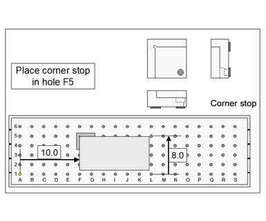
First, the external work offset should be applied when you know (or can easily calculate) the distance from a known/consistent position to each program origin. With a vertical machining center, for instance, you may be mounting qualified workholding tooling on a subplate like the one shown in the illustration to the right.
With this kind of workholding tooling, you can easily calculate the distance in X and Y between location surfaces (the XY program origin) to the lower-left hole. With this example, the holes are on precise 2-inch centers. You can also determine the distance in the Z axis between the Z-axis location surface and the top of the subplate.
In the external work offset X and Y registers, enter the distances in X and Y from the machine’s home position to the lower-left hole (hole A1). In the Z register, enter the distance from the spindle nose to the subplate top. From this point on, your fixture offset entries can be specified from the lower-left hole in XY and the top of the subplate in Z.
This will eliminate the need to measure program origin assignment values. Of course, you can use the data setting command (G10) to specify the related values from within the program, eliminating the need for the setup person to manually enter them. This effectively eliminates that task of program zero assignment from setup.
The second time the external offset can help is with horizontal machining centers that have square rotary tables. The location surfaces for most fixtures are dimensioned from table center. So, it may be best to shift the point of reference to the table center in XY and the tabletop in Z. In this way, the program zero assignment values can be determined from the fixture drawing. Again, these entries can be programmed with G10 commands.
Third, the external work offset can help you deal with spindle taper inconsistencies from one machining center to another. If you find it necessary to use different tool length compensation values for a given cutting tool based on which machine is being used, use the external offset (Z register) to specify the amount of discrepancy. In this way, cutting tools can be more easily shared among machines.
Fourth, if you have had a mishap (crash), you may find the axes to be slightly out of alignment, meaning program zero assignment values for qualified setups are no longer correct. Use the external work offset to specify the amount of misalignment in each axis. For the subplate example described earlier, this will be as simple as remeasuring the XY distances to the lower left hole and the top of the subplate in Z.
Fifth, you can increase the Z-axis register of the external work offset when dry running to keep cutting tools further away from their Z-axis end points. This makes for a safer dry run.


Related Content

AI Servo Tuning Explained: How CNC Machines Optimize Motion Automatically
What FANUC calls AI Servo Tuning is changing how machines behave before their first cut — even though most machinists will never touch it.
Read More
Advanced Tool Paths, Simple Implementation
Programming advanced tool paths used to be a complex, time-consuming task. Canned cycles in CAM software have now made them more accessible than ever.
Read More
Continuous Improvement and New Functionality Are the Name of the Game
Mastercam 2025 incorporates big advancements and small — all based on customer feedback and the company’s commitment to keeping its signature product best in class.
Read More
How I Made It: Mike Lynch
Mike Lynch has been a CNC programming teacher for three decades, in addition to being the longest-running columnist in Modern Machine Shop history, providing generations of machinists with expert insight into the art of programming parts. With this issue being Mike’s last, we wanted to highlight his career and what it means for the industry.
Read MoreRead Next

WEBINAR: From Machine Data to Guided Action: How Modern Shops Are Closing the Execution Gap
In this webinar, MachineMetrics Product Manager Josh Fish is joined by Pindel Global Precision's Thomas Deslongchamps, for a candid look at what closing the execution gap actually looks like inside a precision machining shop.
Read More

