
How Modal Testing Can Reveal Dynamic Machining Responses
Tool-holder-spindle-machine combinations each have a unique dynamic response in the same way that each person has a unique fingerprint, which can be revealed using modal testing.


The digital manufacturing process begins with a part design that is represented by a digital, three-dimensional model. When machining is the manufacturing process, the model dimensions, tolerances and materials inform decisions on workpiece stock, cutting tool and toolholder, machining center, workholder and coolant. The CAM step uses the part and stock models, as well as the selected cutting tools, to generate toolpaths that remove material and reveal the desired geometry. This sequence of events suggests that machining is a fully geometric process.
While geometry is important, machining is more than geometry. When selecting the CAM parameters, including step over (radial depth of cut), step down (axial depth) and spindle speed, the dynamic response of the toolholder-spindle-machine combination, and sometimes the workpiece, must be considered. This is due to the vibrations that occur during machining, which can be characterized as forced vibration and self-excited vibration.


In forced vibration, the cutting force and corresponding vibration repeat from one tooth to the next, providing a consistent surface finish. In self-excited vibration, the inherent feedback mechanism in machining causes the process to become unstable, which is referred to as chatter. The feedback mechanism is possible because the tool vibration is imprinted on the workpiece surface, causing chip thickness to vary from one tooth to the next. This represents “memory” in the machining process. The variable chip thickness leads to a variable force which, in turn, affects the current vibration. Whether we obtain forced vibration (good vibration) or chatter (bad vibration) depends on the spindle speed-depth of cut combination and the toolholder-spindle-machine dynamics.
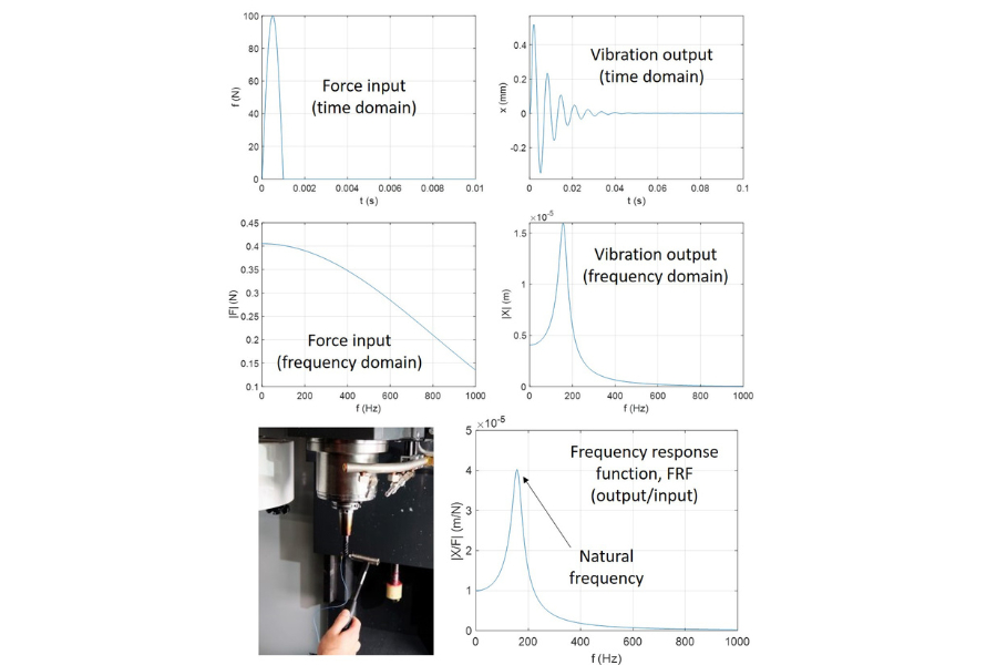
So… how do we know which combinations cause chatter and which do not? The required information is contained in the frequency response function, or FRF. This describes the vibration response divided by the force input in the frequency domain. With the FRF, we can identify the natural frequency, stiffness and damping for each vibration mode.
To measure the FRF, we use modal testing, also referred to as tap testing. The figure above identifies the key elements of the test. The lower left photograph shows a modal hammer being used to tap a tool tip and an accelerometer being used to measure the vibration response. The top row displays the time responses for the force and vibration. We see that the tap produces a short duration force input. Due to this impulse, the tool vibrates with a decaying amplitude (due to damping).
The middle row shows the conversion of these signals to the frequency domain. The bottom row displays the FRF. As stated, we can identify the natural frequency, stiffness and damping for each vibration mode (only a single mode is shown in this example). The value of this information is that we can use it to generate a stability map that separates spindle speed-depth of cut combinations that produce chatter from those that do not. When this information is available at the process planning stage, the test-and-check approach of confirming part programs can be reduced or eliminated. In this way, we move the “fingerprint” of the toolholder-spindle machine into the digital environment and make digital manufacturing possible.


Related Content

How Transparency Can Help Machine Shops Become More Efficient
Here are three areas that a machine shop owner can use to both share information and gather new information that would help them become more efficient and effective.
Read More
Make the Most of Your Interactions With Salespeople
Don’t miss out on products and knowledge that could help your company.
Read More
Rethink Quality Control to Increase Productivity, Decrease Scrap
Verifying parts is essential to documenting quality, and there are a few best practices that can make the quality control process more efficient.
Read More
Sharing the Manufacturing Narrative With Policymakers
Conversations with policymakers represent a chance to communicate our challenges, showcase our passion and impact them with our pride in American manufacturing.
Read MoreRead Next


3 Mistakes That Cause CNC Programs to Fail
Despite enhancements to manufacturing technology, there are still issues today that can cause programs to fail. These failures can cause lost time, scrapped parts, damaged machines and even injured operators.
Read More
The Cut Scene: The Finer Details of Large-Format Machining
Small details and features can have an outsized impact on large parts, such as Barbco’s collapsible utility drill head.
Read More