
A Spiral Milling Custom Macro Using Constant Contouring Feedrate
Helical milling or “spiral” milling are helpful when machining a circular pocket that is much larger than the milling cutter diameter.
.jpg;width=70;height=70;mode=crop;format=webp)


Milling a circular pocket is a very common machining center operation. Accepted practices include helical milling (circular XY motion with linear Z motion) and “spiral” milling (XY-circular motion after positioning in the Z-axis). These methods are especially helpful when the circular pocket being machined is quite large — much larger than the milling cutter diameter when multiple XY- and Z-axis passes are required. Chad Kluth of Mid Valley Industries provided suggestions and help with verification.
Features of this spiral milling FANUC Custom Macro include climb or conventional milling, as well as constant contouring feedrate. Additionally, if a prior hole exists that is larger than the milling cutter diameter, the milling cutter will rapid during Z-axis plunging motions. If the surface is solid — or if the hole is smaller than the cutter diameter — the cutter fill feed at half the XY-axes machining feedrate when plunging in the Z-axis.


Figure 1 shows several of the input values.
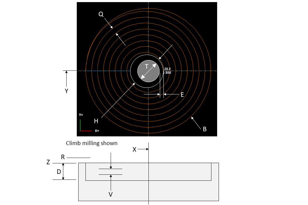
Here are all the letter address arguments in the G65 calling command, their local variable representations and brief descriptions of their meanings:
- X #24: X-axis center of the hole
- Y #25: Y-axis center of the hole
- Z #26: Z-axis surface into which to mill
- R #18: Z-axis rapid approach distance from surface, default is 0.1 inch
- D #7: Depth of pocket
- V #22: Z-axis depth per pass
- B #2: Big/final diameter
- H #11: Hole diameter — if solid, leave H out of the calling command
- E #8: XY-axes approach distance when there is a hole
- F #9: XY- axes milling feedrate
- U #21: Fast feedrate, used when moving back to starting position
- C #3: Milling style — C1.0 or leave C out of call for climb, C2.0 for conventional
- T #20: Tool diameter
- Q #17: XY-axes stock removal per pass
- W #23: Constant contouring feedrate, leave out of call or set to 0 for no, set to 1. for yes
This is an example calling program that includes the calling G65 command:
- O0001
- N005 T01 M06
- N010 G54 G90 S600 M03
- N015 G00 X0 Y0
- N020 G43 H01 Z0.2 M08
- N025 G65 P1000 X0 Y0 Z0 D0.5 R0.2 F5.0 U30.0 H4.0 E0.1 C1.0 B6.0 T1.0 Q0.2 V0.2 W1.0
- N030 G91 G28 X0 M09
- N035 G28 Z0 M19
- N040 M30
It will use a 1.0-inch diameter end mill and machine a circular pocket at X0 Y0 from the hole diameter of 4.0 inches to its final diameter of 6.0 inches using a 0.2 XY-axes step-over per pass. The pocket will be machined 0.5-inch deep while taking 0.2-inch depths per pass. The pocket will be climb milled and constant contouring feedrate will be used. Most of the argument descriptions are self-explanatory. But a couple may need further clarification:
- If you want only one Z-pass, set the depth per pass (V) to the same value as the circular pocket depth (D).
- If constant contouring feedrate is not used (W0), then the XY-machining feedrate (F) will be used for all circular motions. If it is used (W1.0), the feedrate for each circular motion will be reduced to ensure that the milling cutter is not overloaded.
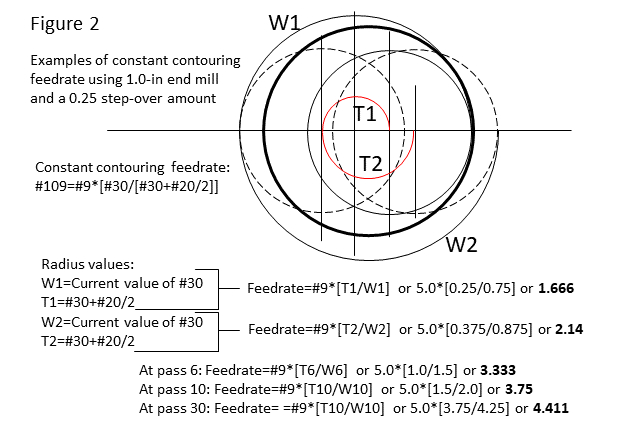
Whenever a milling motion is specified in the X- and/or Y-axes, the specified feedrate will be based upon the milling cutter’s centerline path. For linear motions, this is fine since the milling cutter’s periphery will move the same distance as its centerline. But with circular motions, the centerline path will be different than the milling cutter’s periphery path. For internal arcs, the centerline path will be shorter. It will be longer for external radius milling.
This means the centerline path feedrate must be slowed when making internal circular motions if the programmed feedrate is to be the rate of motion at the milling cutter’s periphery. The bigger the cutter radius, the more slowing will required. See Figure 2 to see how this applies to the spiral milling Custom Macro circular movements.
Here is the spiral milling Custom Macro:
- O0051 (SPIRAL MILLING CUSTOM MACRO)
- (DEFAULTS)
- IF[#18EQ#0] THEN #18=0.1 (DEFAULT TO 0.1 R-PLANE)
- IF[#3EQ#0] THEN #3=1.0 (DEFAULT TO CLIMB)
- IF[#23NE1.0] THEN #109=0 (DEFAULT TO NO CONSTANT CONTOURING FEEDRATE)
- IF[#8EQ#0]THEN #8=0.2 (DEFAULT XY APPOACH TO 0.2)
- (MANDATORY ARGUMENTS)
- IF[#24EQ#0]THEN #3000=100(X MISSING IN CALL)
- IF[#25EQ#0]THEN #3000=101(Y MISSING IN CALL)
- IF[#26EQ#0]THEN #3000=102(Z MISSING IN CALL)
- IF[#7EQ#0]THEN #3000=103(D MISSING IN CALL)
- IF[#9EQ#0]THEN #3000=104(F MISSING IN CALL)
- IF[#21EQ#0]THEN #3000=105(U MISSING IN CALL)
- IF[#2EQ#0]THEN #3000=106(B MISSING IN CALL)
- IF[#20EQ#0]THEN #3000=107(T MISSING IN CALL)
- IF[#17EQ#0]THEN #3000=108(Q MISSING IN CALL)
- IF[#22EQ#0]THEN #3000=109(V MISSING IN CALL)
- (ALARM CHECKS)
- IF[#11EQ#0] GOTO 1
- IF[[#11/2-#20/2] LE #8]THEN #3000=110(HOLE TOO SMALL)
- (HOLE OR NO HOLE)
- N1 IF[#11NE#0]GOTO 2
- (HOLE OR NO HOLE)
- IF[#11NE#0]GOTO 2
- #100=1 (NO HOLE)
- GOTO 3
- N2#100=0 (HOLE)
- N3 (CLIMB OR CONVENTIONAL)
- IF[#3EQ1.0] GOTO5 (CLIMB)
- IF[#3EQ2.0] GOTO 6 (CONVENTIONAL)
- #3000=100 (INVALID C VALUE IN CALL)
- N5 (CLIMB)
- #27=1.0 (MULTIPLIER FOR CLIMB/CONVENTIONAL)
- #28=3 (G-CODE FOR CLIMB)
- GOTO 8
- N6 (CONVENTIONAL)
- #27=0-1.0 (MULTIPLIER FOR CLIMB/CONV MIRROR MOTION)
- #28=2 (G-CODE FOR CONVENTIONAL)
- (INITIAL MOTIONS)
- N8
- (SOLID OR WITH HOLE)
- IF[#11EQ#0] GOTO 50 (SOLID)
- (WITH HOLE)
- #121=#24+[[#11/2-#20/2-#8]*#27]
- G90 G00 X#121 Y#25 F#21
- Z[#26+#18]
- (Z LOOP)
- #101=FUP[#7/#22] (NUMBER OF Z PASSES]
- #22=#7/#101 (RECALCUALATED DEPTH PER PASS)
- #102=#26-#22 (CURRENT Z DEPTH)
- #103=1.0 (Z COUNTER)
- N9 IF[#103 GT #101] GOTO 90
- G90 G#100 Z#102
- (XY LOOP)
- #33=[#2/2]-#11/2 (STOCK TO REMOVE ON SIDE)
- #32=FUP[#33/#17] (NUMBER OF FULL CIRCLE XY STEPS)
- #107=[#33/#32]/2 (RECALCULATED STEP OVER AMOUNT FOR HALF CIRCLE)
- #31=[#11/2-#20/2]*#27(CURRENT X POSITION FOR LOOP)
- #29=1.0 (COUNTER)
- G91 G01 X[#8*#27] F#9
- #31=#31*2
- N10 IF[#29GT#32] GOTO 30
- #31=[ABS[#31]+#107*2]*#27*[0-1]
- #30=#31/2
- IF[#23NE1.0]THEN #109=#9 (NO CCF)
- IF[#23EQ1.0]THEN #109=#9*[ABS[#30]/[ABS[#30]+#20/2]] (CCF)
- G91 G#28 X#31 I#30 F#109
- #31=[ABS[#31]+#107*2]*#27
- #30=#31/2
- IF[#23NE1.0]THEN #109=#9 (NO CCF)
- IF[#23EQ1.0]THEN #109=#9*[ABS[#30]/[ABS[#30]+#20/2]] (CCF)
- G91 G#28 X#31 I#30 F#109
- #29=#29+1.0
- GOTO 10
- (FINISH CIRCLE AND GO BACK TO START POINT)
- N30 G91 G#28 X-#31 I-#30 F#109
- #27=#27*[0-1]
- #121=#24+[[#11/2-#20/2-#8]*#27]
- G90 G01 X#121 Y#25 F#21
- (STEP Z LOOP VALUES)
- #103=#103+1
- #102=#102-#22
- GOTO 9
- GOTO90 (SKIP SOLID)
- N50 (SOLID)
- G90 G00 X#24 Y#25
- G90 G00 Z[#26+#18]
- (Z LOOP)
- #101=FUP[#7/#22] (NUMBER OF Z PASSES]
- #22=#7/#101 (RECALCUALATED DEPTH PER PASS)
- #102=#26-#22 (CURRENT Z DEPTH)
- #103=1.0 (Z COUNTER)
- N52 IF[#103 GT #101] GOTO 90
- G90 G00 X#24 Y#25
- G#100 Z#102 F[#9/2]
- (XY LOOP)
- #33=#2/2-#17-#20/2 (STOCK TO REMOVE ON THE SIDE)
- #32=FUP[#33/#17] (NUMBER OF XY STEPS)
- #107=[#33/#32]/2 (RECALCULATED STEP MOVE OVER AMOUNT)
- #31=#17*#27(STARTING X POSITION)
- #30=#31/2
- #29=1 (COUNTER)
- IF[#23NE1.0]THEN #109=#9 (NO CCF)
- IF[#23EQ1.0]THEN #109=#9*[ABS[#30]/[ABS[#30]+#20/2]] (CCF)
- G91 G#28 X#31 I#30 F#109
- (MILL CENTER HOLE)
- #30=#30*2
- IF[#23NE1.0]THEN #109=#9 (NO CCF)
- IF[#23EQ1.0]THEN #109=#9*[ABS[#30]/[ABS[#30]+#20/2]] (CCF)
- I-[#30] F#109
- #31=#31*2
- N60 IF[#29GT#32] GOTO 80
- #31=[ABS[#31]+#107*2]*#27*[0-1]
- #30=#31/2
- IF[#23NE1.0]THEN #109=#9 (NO CCF)
- IF[#23EQ1.0]THEN #109=#9*[ABS[#30]/[ABS[#30]+#20/2]] (CCF)
- G91 G#28 X#31 I#30 F#109
- #31=[ABS[#31]+#107*2]*#27
- #30=#31/2
- IF[#23NE1.0]THEN #109=#9 (NO CCF)
- IF[#23EQ1.0]THEN #109=#9*[ABS[#30]/[ABS[#30]+#20/2]] (CCF)
- G91 G#28 X#31 I#30 F#109
- #29=#29+1.0
- GOTO 60
- N80 (FINISH CIRCLE AND GO BACK TO CENTER)
- IF[#23NE1.0]THEN #109=#9 (NO CCF)
- IF[#23EQ1.0]THEN #109=#9*[ABS[#30]/[ABS[#30]+#20/2]] (CCF)
- G#28 X-#31 I-#30 F#109
- G90 G01 X#24 Y#25 F#21
- (STEP Z VALUES)
- #103=#103+1
- #102=#102-#22
- GOTO 52
- N90 G00 Z[#26+#18]
- M99


Read Next

Obscure CNC Features That Can Help (or Hurt) You
You cannot begin to take advantage of an available feature if you do not know it exists. Conversely, you will not know how to avoid CNC features that may be detrimental to your process.
Read More
The Cut Scene: The Finer Details of Large-Format Machining
Small details and features can have an outsized impact on large parts, such as Barbco’s collapsible utility drill head.
Read More
3 Mistakes That Cause CNC Programs to Fail
Despite enhancements to manufacturing technology, there are still issues today that can cause programs to fail. These failures can cause lost time, scrapped parts, damaged machines and even injured operators.
Read More