
Centralization Errors Grow as Bores Get Smaller
It is important to consider the effects of gage centralization when measuring smaller bores. Selecting the right tool is often based on the bore’s size and tolerance.

Share


There are many ways to measure a bore, and many factors that influence the accuracy of hole diameter measurements. For example, we know that operator skill in using rocking-type adjustable bore gages can influence the results, as can variations in part geometry. This may make even technically accurate measurements inaccurate from a part-function perspective, so it is important to consider the effects of gage centralization for smaller bores. Selecting the right tool is often based on the bore’s size and tolerance.
One of the fundamental requirements in bore gaging is that the gage contacts be centered in the bore. Bore gages that are not properly centered measure a chord of the circle rather than its true diameter. Operator error is a common cause of poor centralization with rocking-type gages, while wear or damage can affect the centralization of any gage.


An adjustable bore gage may be the gage of choice for bores with a tolerance of 0.002" or more. Most adjustable bore gages have a centralizer that helps the operator align the gage properly, and with good operator skill, good results can be obtained. However, should the centralizer or sensitive contact be damaged, there will be a likelihood of some gage influence on the results. Centralization errors can be checked by comparing the results of mastering on a ring gage and then checking with end standards.
Once tolerances start to get less than 0.001", a fixed-body plug gage is apt to be right for the application. Fixed-body plug gages, such as mechanical two-point plug gages or two-jet air plugs (or air rings), are designed to be self-centering. These fixed-body gages are designed with very specific clearances based on the combination of bore size and tolerance. The engineered clearance between the gage body and the nominal size of the bore is really a compromise between ease of insertion and optimum centralization to reduce this error.
Centralization error is the difference between the true diameter and the length of the chord measured. Quality personnel and gage designers specify centralization error as a percentage of a gaging operation’s total error budget (or repeatability requirement). For example, the error budget might be 10% of the tolerance. In addition to an allowance for centralization error, this might include influences of operator error, gage repeatability, environmental variation and within-part variation (for example, geometry error).
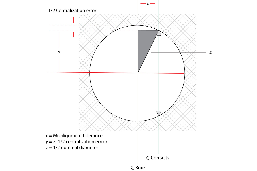
Gage manufacturers and users must be prepared to calculate how far off the bore center line a gage may be without exceeding the specified centralization error. Let’s call the allowable distance between the bore center line and the contact center line the misalignment (clearance) tolerance. A simple formula based on the relationship between the legs and the hypotenuse of a right triangle does the job:
x2 = z2 - y2
where:
x = misalignment tolerance
y = z - 1/2 centralization error
z = 1/2 nominal diameter
Let’s run through an example. The nominal bore dimension is 0.5", with a dimensional tolerance of 0.0002" (±0.0001"). Since the goal may be to get the total gage error to less than 10% of tolerance, it would not be unreasonable to let centralization error be specified at a maximum of 2% of the dimensional tolerance (or 0.02 x 0.0002" = 0.000004").
z = 0.5" ÷ 2 = 0.250"
y = 0.250" - (0.00004" ÷ 2) = 0.249998"
x2 = (0.250")2 - (0.24998")2
x2 = 0.0625" - 0.062499"
x2 = 0.000001"
x = 0.001"
The gage must have less than 0.001" clearance or be off-center before it exceeds the allowable centralization error. If you run through the same exercise for a 5.0" nominal bore, keeping the other values constant, you’ll find that misalignment can be up to 0.0031" before centralization error exceeds 2% of the 0.0002" dimensional tolerance. Thus, as bore size increases, so does the misalignment tolerance. But on the other hand, measuring smaller bores with a tight tolerance requires very tight clearances to eliminate centralization errors.
For the smaller diameters — say, less than 1" — it is important to monitor this error. As one can expect, with years of use measuring hundreds of thousands of parts, the plug may become worn, resulting in excessive clearance and poor centralization.
Checking centralization is easy for self-centering gage types. To check a two-contact or two-jet plug, insert the gage horizontally into a master ring, allowing the master to bear the gage’s weight. For an air ring, one can do the same test with the master disc. Measure once with the contacts or jets oriented vertically and once horizontally. If the measurements differ, and a significant portion of the tolerance, it may be time to replace.


.png;maxWidth=300;quality=90;format=webp)
Related Content

Orthopedic Event Discusses Manufacturing Strategies
At the seminar, representatives from multiple companies discussed strategies for making orthopedic devices accurately and efficiently.
Read More
Turning Fixed-Body Plug Gages Inside Out
Fixed-body mechanical plug gages provide fast, high-performance measurement for tight-tolerance holes.
Read More
Using Digital Tap Testing to Measure Machining Dynamics
Tool-toolholder-spindle-machine combinations each have a unique vibration response. We can measure the response by tap testing, but we can also model it.
Read More
Using Air to Measure Squareness
Though most frequently used for diameter measurements, an air plug and platen can be readily configured to measure perpendicularity.
Read MoreRead Next

OEM Tour Video: Lean Manufacturing for Measurement and Metrology
How can a facility that requires manual work for some long-standing parts be made more efficient? Join us as we look inside The L. S. Starrett Company’s headquarters in Athol, Massachusetts, and see how this long-established OEM is updating its processes.
Read More