High Feed Rates or Deep Cuts - Which is Faster?
Sponsored ContentComparing high-feed milling to other kinds, it is clear that the high feed and metal removal rates deliver on promises, but sometimes slowing down the feed and increasing the depth of cut will still end up faster.
Share
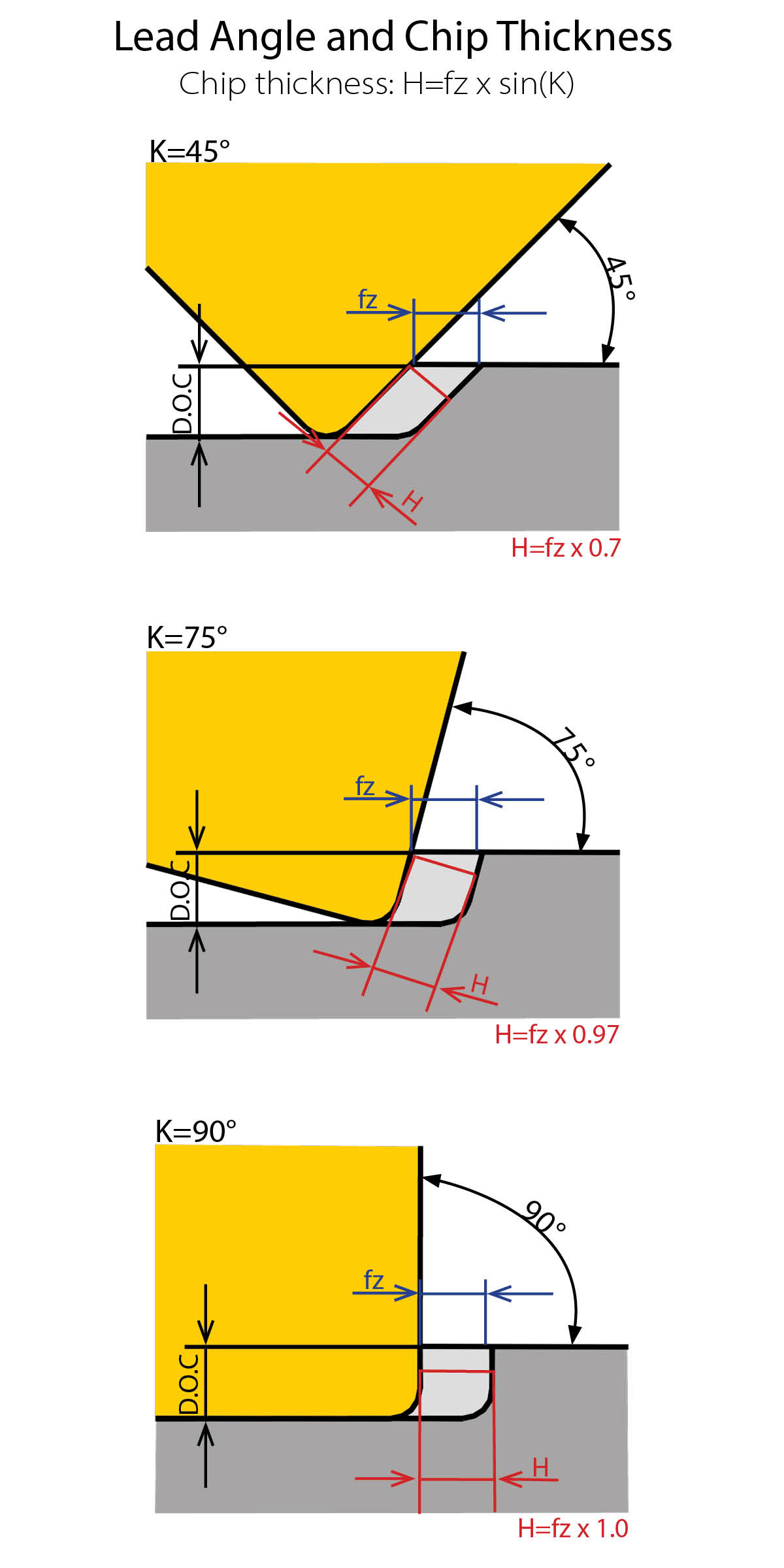
High-feed milling is possible due to the effect of chip thinning resulting from the shallow lead angle of the cutter – typically 10 to 25 degrees. The smaller the lead angle, the more the feed can be increased and still maintain the recommended chip thickness. For example, with a 90-degree cutter with at least 50% radial engagement, the chip thickness equals the feed per tooth (fz). With a 45-degree cutter, the chip thickness is only 70% fz, and if the lead angle is only 10 degrees, then tit is only 17% of fz. The downside is that as the lead angle increases, the depth of cut capability decreases. The higher feeds often translate to high metal removal rates making high-feed milling a very productive and cost effective method to quickly rough machine a variety of workpieces.
However, high metal-removal rates and feed rates do not tell the whole story. The reduced depth of cut can mean a much larger number of machining passes, which can lead to time lost to repositioning. To determine under what conditions a machinist would prefer to pursue maximum feed rates versus maximum depth of cut, Kyocera performed a study comparing the different milling strategies.
Another advantage of high-feed milling is a reduced tendency for chatter, especially with longer overhangs. The majority of the cutting forces are directed axially due to the lead angle, resulting in less deflection and chatter. Kyocera’s MFH-family of high-feed cutters also have a convex cutting edge design that further reduces cutting force and vibration.
There are a wide variety of indexable high-feed cutter designs available in the marketplace, which can potentially create confusion for endusers when trying to select the best option. To help illustrate some key differences, Kyocera selected a typical machining scenario (decking a 4140 workpiece, 28-32 Rc, 5×6", 0.090" total to be removed) and evaluated three different 2-inch high-feed cutters to see which was most productive. Let’s take you through the selection process so you can see what needs to be considered when selecting a high-feed cutter to meet your needs.
The Cutters
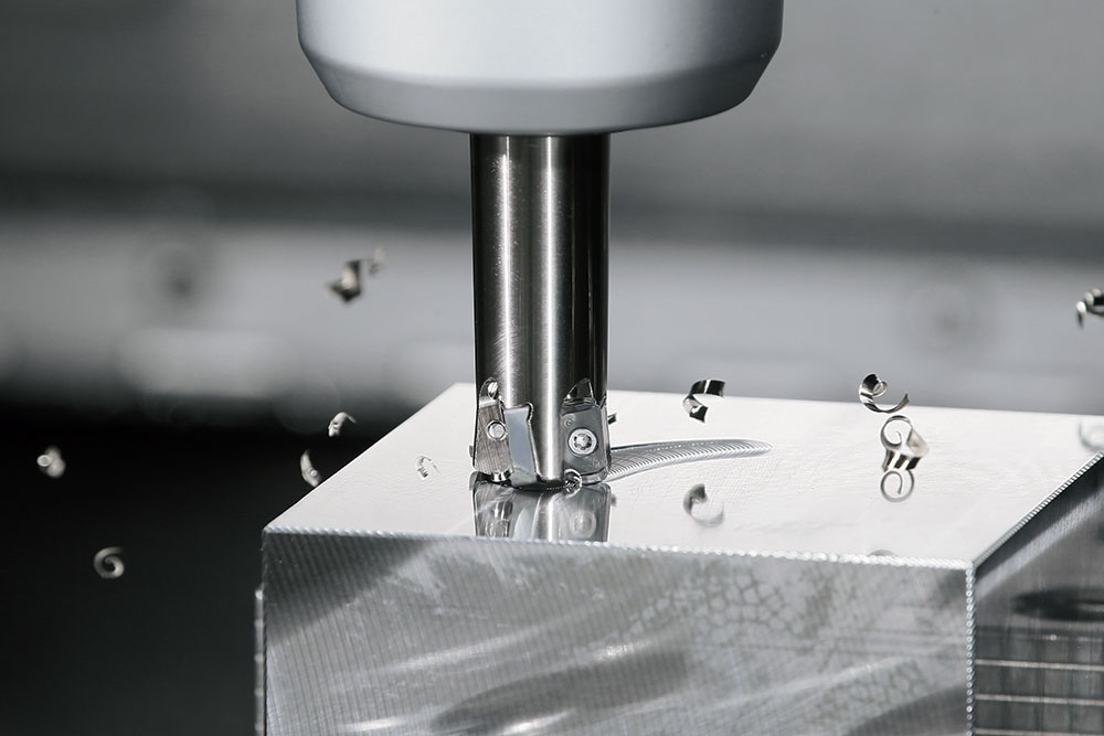
The 2-inch Kyocera MFH Raptor MFH2000R-14-4T was one of the cutters used in this high-feed milling test
- 2" MFH Raptor MFH2000R-14-4T (4 flute, SOMT14 inserts)
-
- DCX (max diameter to outer insert edge): 2"
- DC (cutting diameter): 1.094"
- APMX (max depth of cut): 0.079"
- 2" MFH Mini MFH2000R-03-9T (9 flute, LOGU03 inserts)
-
- DCX: 2"
- DC: 1.685"
- APMX: 0.039"
- 50-mm MFH Max MFH050R-04-7T-M
-
- DCX: 1.969"
- DC: 1.535"
- APMX: 0.098"
High-feed cutters are no different than any other cutter with anything but a 90-degree lead angle – you need to pay attention to the DC dimension – which governs the flat portion machined – and the APMX value (maximum depth of cut). Knowing these dimensions, an engineer can calculate how many passes are needed with each cutter to face our part to a 0.090-inch depth.
|
Cutter |
DCX |
DC |
APMX |
# of passes (Ae) |
# of passes (Ap) |
Total # of passes |
|
MFH2000R-14-4T (MFH-Raptor) |
2.000 |
1.094 |
0.079 |
6 | 2 |
12 |
|
MFH2000R-03-9T (MFH-Mini) |
2.000 |
1.685 |
0.039 |
4 | 3 |
12 |
|
MFH050R-04-7T-M (MFH-Max) |
1.969 |
1.535 |
0.098 |
4 | 1 | 4 |
|
MFH050R-04-7T-M_2 (MFH-Max) |
1.969 |
1.535 |
0.098 |
4 | 2 | 8 |
Taking the MFH2000R-14-4T Raptor as the example you can see that it will take 6 passes to face the part since the DC dimension is just over one inch. Additionally, since APMX is less than 0.090” it will require 2 passes in the Z-direction to get to the full depth. This results in 12 passes total to machine to the desired dimension (6 × 2 = 12). The MFH Mini has a greater DC dimension but a smaller APMX and the result is also a total of 12 passes. Kyocera considered 2 options with the MFH Max. It is capable of taking the full 0.090-inch depth of cut resulting in four passes total (but at a reduced feed). The company also evaluated taking 2 0.045-inch passes (eight passes total) at a higher feed.
For the purposes of this evaluation, they used the same carbide grade (PR1535) in each cutter and ran each at the recommended starting points for speed and feed.
|
Cutter |
VC |
RPM |
Fz |
Vf |
Ap |
MRR |
|
MFH2000R-14-4T (MFH-Raptor) |
500 |
955 |
0.059 |
225.4 |
0.045 |
10.03 |
|
MFH2000R-03-9T (MFH-Mini) |
500 |
955 |
0.030 |
257.9 |
0.030 |
11.48 |
|
MFH050R-04-7T-M (MFH-Max) |
500 |
970 |
0.010 |
67.9 |
0.090 |
9.07 |
|
MFH050R-04-7T-M_2 (MFH-Max) |
500 |
970 |
0.022 |
147.1 |
0.045 |
9.82 |
The two most common measurements of productivity are the table feed (Vf) and metal removal rate (MRR) shown in the chart above. Table feed is easily seen and everyone likes to brag about how fast they can run a cutter (like ¼ mile times or top speed of an automobile). However, speed doesn’t tell the whole story (who wants to drive a drag car on a winding mountain road). The metal removal rate is usually a more accurate representation of productivity as it is a measurement of how much material is removed per minute of cutting time. It is a function of table feed, depth (Ap) and width (Ae) of cut. In our study it just so happened that the ranking of Vf and MRR is the same for each cutter. However, you can see that while the Vf of the MFH050R-04-7T-M (67.9 cubic inches per minute) is approximately one quarter that of the MFH2000R-03-9T (257.9), the metal removal rate is 79% (9.07 compared to 11.48). Using either measurement one would expect to see the MFH Mini come out on top followed by the MFH Raptor and the MFH Max at the bottom. What these don’t take into consideration is the non-cutting time (rapid moves to reposition for additional passes). As the number of passes increase, the number of positioning moves necessary also increases.
The Results
- MFH2000R-14-4T
|
Cutter |
Cycle Time |
Total # of passes |
VC |
Vf |
Ae |
Ap |
MRR |
|
MFH2000R-14-4T (MFH-Raptor) |
00:00:34:27 |
12 |
500 |
225.4 |
0.989 |
0.045 |
10.03 |
- MFH2000R-03-9T
|
Cutter |
Cycle Time |
Total # of passes |
VC |
Vf |
Ae |
Ap |
MRR |
|
MFH2000R-03-9T (MFH-Mini) |
00:00:31:24 |
12 |
500 |
257.9 |
1.484 |
0.030 |
11.48 |
- MFH050R-04-7T-M (0.090" Ap)
|
Cutter |
Cycle Time |
Total # of passes |
VC |
Vf |
Ae |
Ap |
MRR |
|
MFH050R-04-7T-M (MFH-Max) |
00:00:30:23 |
4 |
500 |
67.9 |
1.484 |
0.090 |
9.07 |
- MFH050R-04-7T-M (0.045" Ap)
|
Cutter |
Cycle Time |
Total # of passes |
VC |
Vf |
Ae |
Ap |
MRR |
|
MFH050R-04-7T-M_2 (MFH-Max) |
00:00:31:26 |
8 |
500 |
147.1 |
1.484 |
0.045 |
9.8 |
Comparing the cutters with 12 total passes we can see that the option with the higher table feed and MRR came out on top. While this is a specific case it shows that not only table feed (Vf) and MRR should be considered, but we also need to look at the total number of required passes and the non-cutting time when evaluating overall cycle times. Changes in the overall dimensions of our workpiece or the total stock removal would impact the results seen here. You’ll need to consider your unique situation to determine the optimal high-feed cutter to match your particular workpiece.You can see that in this case the fewest number of passes more than offset the difference in table feed (Vf) or MRR allowing the MFH050R-04-7T-M cutter taking the full 0.090" depth to achieve the shortest cycle time (30.23 seconds). The MFH2000R-03-9T and MFH050R-04-7T-M (0.045" Ap) taking 12 and 8 total passes, respectively, resulted in almost identical cycle times (31.24 and 31.26). The MFH2000R-14-4T (second-highest Vf and MRR) ended up with the longest cycle time due to the high number of passes.
Wear Test
Next we’ll take a look at how feed and depth of cut affect tool life. The test has shown that in some instances a lower feed at a larger depth of cut can provide shorter cycle times compared to running a light depth of cut at a heavier feed. Which option is best for tool life or will there be any difference?
To find out, Kyocera continued testing on 4140 blocks with a hardness of 28 – 32 Rc. To determine the test parameters, an MFH3000R-14-6T cutter with SOMT140520ER-GM PR1535 inserts was ran at 520 sfm and the maximum recommended depth of cut, and the feed adjusted until the spindle load reached 100%. The combination of 0.079-inch depth of cut and 0.025 ipt resulted in a spindle load of 100%. At a depth of 0.025 inches and a feed of 0.079 ipt, the spindle load also registered 100% at the same 520 sfm. For the wear portion of the test, an MFH2000R-14-4T cutter was used with an SOMT140520ER-GM PR1535 insert. In order to increase the wear rate, they ran at 800 sfm which was a little higher than the maximum recommended cutting speed of 720 sfm. The width of cut (ae) was 1 inch. The first test was run at a depth (ap) of 0.025 inches and feed (fz) of 0.079 ipt.
MFH3000R-14-6T, Fz = 0.025 ipt, D.O.C. = 0.079"
The second test was at a depth (ap) of 0.079 inches and a feed (fz) of 0.025 ipt. This resulted in identical metal removal rates. All tests were performed without coolant. Wear was measured at 10 minute intervals until reaching 90 minutes of cutting time.
MFH3000R-14-6T, Fz = 0.079 ipt, D.O.C. = 0.025"
Wear Results
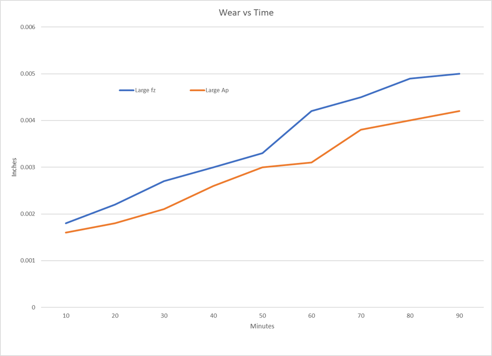
Below is a plot of the insert wear over the duration of the test. The blue line represents the high feed – low ap result and the orange line represents the high ap – low feed result. As you can see, the high ap – low feed cutting conditions resulted in less wear after 90 minutes of cutting time.
And here are photos of the inserts at the end of the test:
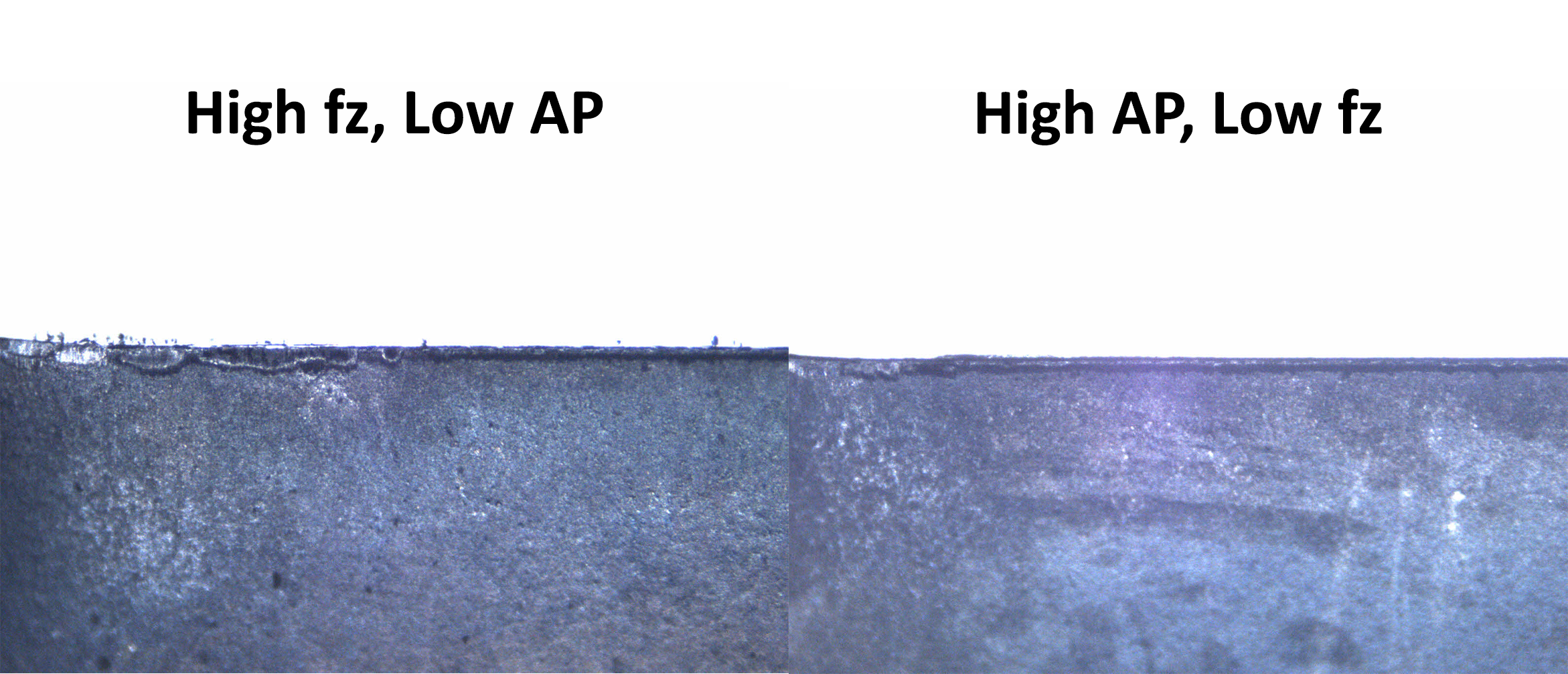
The simulated results below closely follow the actual evaluation. You can see that the heat and stresses generated are much higher at the lighter depth of cut and higher feed. They are also concentrated in a much smaller area and the result is more rapid wear.
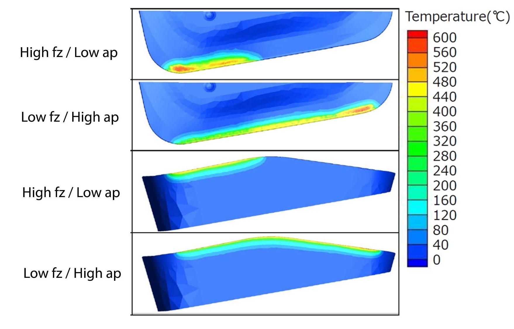
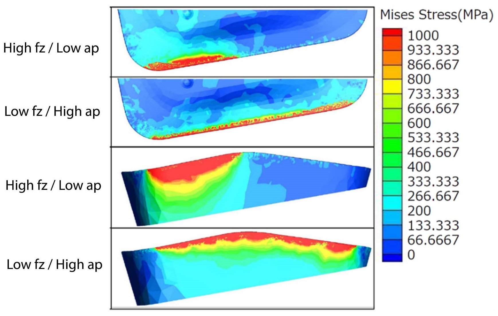
Clearly there are applications where it is advantageous to take a heavier cut at a reduced feed to reduce cycle time and/ or improve tool life. Kyocera’s new MFH Max cutters are designed for applications such as these. They are capable of depths of cut up to 0.098 inches (2.5 mm). While the recommended feed drops as the depth of cut increases it is clear that the MFH Max can offer improvements in both cycle time and tool life. For more information on the MFH-Max, visit the Kyocera Precision Tools website.