
How to Choose the Right Cut Off When Measuring Roughness
Measurement results for surface finishing parameters can vary depending on the filter parameter (Lc), also known as the cutoff.

Share


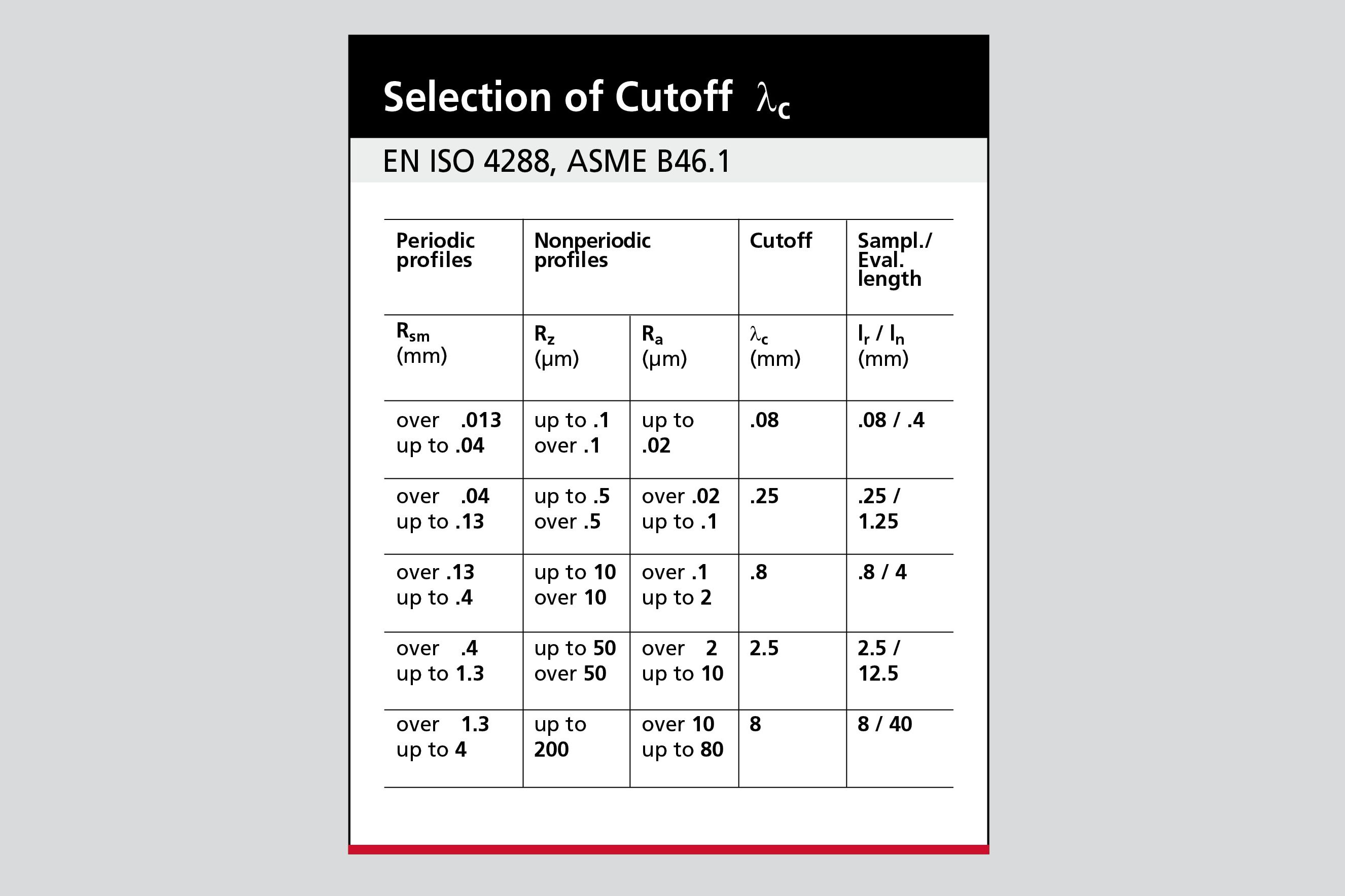
International standards recommend clear rules for which Lc value should be selected given certain parameters. Image: George Schuetz
There are many measuring systems available that bring surface finish measurement to the point of manufacture. Some systems offer the bare minimum to make the operator's measurement process as simple as possible. Others provide virtually the same capabilities of a lab-grade surface analyzer in a portable, handheld surface finish gage.
Having so much power in a handheld measuring system is a great feature, unless the results are not really what the surface represents. For example, a user will perform a roughness measurement, and the value of the Rz or other roughness parameter will look perfectly satisfactory. But there is a bit of an issue when it comes to surface finish metrology: the surface finish results for a parameter such as Rz, and all other surface finish parameters, can vary decisively depending on the filter parameter (Lc), also known as the cutoff. With a different Lc value, the results can be different. While these deviations may not be very large, they can still lead to the wrong assessment of the part (as a good or a bad part) because of the surface finish result. Thus, there is a trend in the industry to define setup parameters as part of the finish call-out. But what if it’s a new surface, and not yet defined?


According to surface finish international standard deviations, the shape of a part can be broken down into different orders, or levels. The first order is the form or shape of the part, followed by a waviness component, line roughness and finally area roughness. These orders are not independent, but layered upon one another (for example, roughness will be superimposed on the waviness component).
This is where using Lc, or cutoffs, becomes important. Using cutoffs is a filtering method that provides the means for separating waviness from form, or roughness from waviness. With the proper choice of filtering, the measuring length should be so short that it nearly eliminates any waviness component. In many cases, by observing the measured profile filtered with different Lc (and a bit of experience), one can determine the correct value for the cutoff. But it’s possible to go to the extreme and use too short a filter, which will start to influence the measurement results.
In practice, it’s probably not up to the technician making the measurement to select the correct result. To establish a process that helps to achieve the best results, international standards recommend clear rules for which Lc value should be selected in unknown cases. However, a few basic questions need to be answered to choose the best cutoff Lc.
First, is the test surface made in such a way that the surface is periodic, or aperiodic? Periodic surfaces are characterized by equally spaced, recurring, typical profile characteristics that are clearly visible in both the depiction of the test surface and the profile (in the example, as distinct turning grooves). In contrast, aperiodic profiles do not show any visually striking, special surface structure. In many cases (on milled profiles, for example), not even a distinct working direction can be detected on the surface.
According to the standard, selection of the correct Lc value must be handled differently for periodic surface profiles than for aperiodic ones. In the case of a periodically structured test surface, the value of the mean size of grooves’ RSm must be determined by measurement first. Then, based on widely available charts, the standardized Lc value can be assigned to the measured RSm value.
The charts also have information, should the surface be aperiodic, but it gets a little more complicated. In the aperiodic case, the most suitable Lc value is determined by one of four roughness parameters noted in the selection charts, and may require a series of measurements under different conditions to select the best Lc cutoff. By following the recipe described in the selection charts, the user can narrow down the proper surface finish results.
Fortunately, in most manufacturing environments, periodic surfaces are the norm. But as processes change, designer surfaces become more common or surface tolerances get tighter, knowing the recipe for selecting Lc is increasingly essential.


.png;maxWidth=300;quality=90;format=webp)


Related Content

Measuring Torque, Thrust Force for Smart Drilling Operations
To monitor drilling operations for smart manufacturing solutions, torque and thrust force can be measured.
Read More
Machined Part Geometry Measurement
Uncertain about uncertainty? Having trouble remembering the difference between accuracy and precision? Read on to review key metrology terms relevant to the ISO Guide to the Expression of Uncertainty in Measurement (ISO GUM).
Read More
Marathon Precision’s Engineering Playground: One Shop’s Secret to Sustaining High Tech, Low-Volume and High Morale
Half an airplane on the wall, a ten-foot metal dragon, and a full-blown recording studio might not scream “manufacturing efficiency,” yet Marathon Precision proves otherwise. Here’s how forging, complex CNC operations and staff-driven creative projects combine to fuel the shop’s productivity and profitability.
Read More
Orthopedic Event Discusses Manufacturing Strategies
At the seminar, representatives from multiple companies discussed strategies for making orthopedic devices accurately and efficiently.
Read MoreRead Next

OEM Tour Video: Lean Manufacturing for Measurement and Metrology
How can a facility that requires manual work for some long-standing parts be made more efficient? Join us as we look inside The L. S. Starrett Company’s headquarters in Athol, Massachusetts, and see how this long-established OEM is updating its processes.
Read More