
Let the Tool Path Help the Tool
A cutting tool supplier works in CAM software to create processes that extend tool life and improve performance.
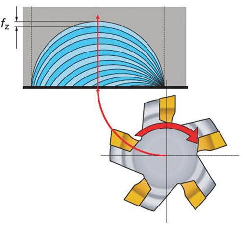
Fig. 1—Roll into the cut by following an arc that curves in the same direction as the tool rotation. This keeps the chip thin at the end of each cutting edge pass.
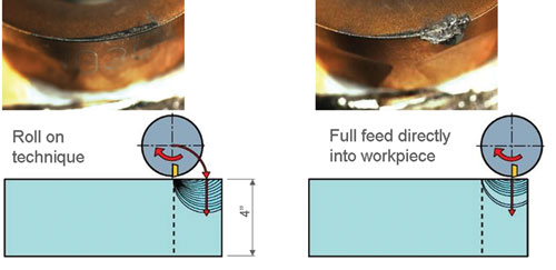
In this comparison involving 100-sfm milling passes in Inconel, rolling into the cut kept tool wear slight after 15 passes (left). Entering the material in a straight line resulted in significant wear after just 2 passes (right).
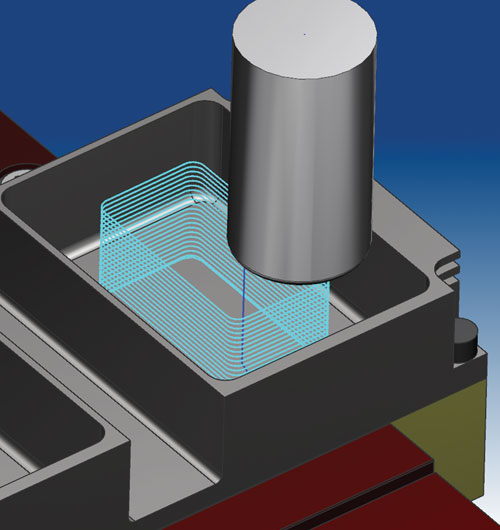
Fig. 2—Continuous ramping keeps the load on the tool consistent, preserving tool life.
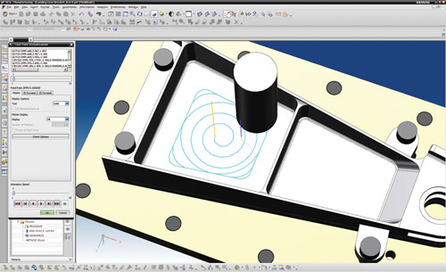
Fig. 3—Even though the pocket is a polygon, the tool path should follow a gradually increasing circle for as long as it can.
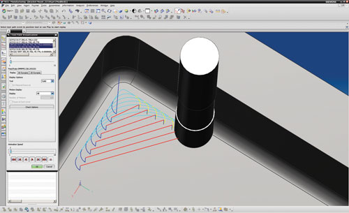
Fig. 4—Corner slicing preserves tool life and makes the process more predictable by replacing cornering tool paths with a progressive series of arcing moves.

Fig. 5—In trochoidal turning, the tool changes direction at the end of every pass to keep the load on the tool more level.
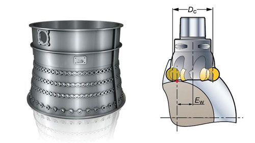
Fig. 6—Milling turbine engine cases with larger-diameter tools involves driving the tool according to a cutting point that actually lands inside the insert’s curvature, indicated here by the red dot on the drawing of the tool.
Share


There is a gap between cutting tool knowledge and the built-in capabilities of even the most advanced CAM systems. The reason for this is simple: The cutting tool makers know the most about the nuances of tool performance. They know more about this than both machine tool suppliers and the developers of software that programs these machines. Forward-moving CAM systems do incorporate new toolpath strategies that have been proven effective. However, as they do this, cutting tool companies continue to search out even more effective strategies for specific machining challenges. This is what progress looks like. As a result, the range of machining strategies that a CAM system can apply automatically is just one aspect of what makes a CAM system valuable. In certain applications involving high-value parts, another valuable aspect of the CAM system is the amount of freedom it offers for departing from these built-in routines.
Tom Funke is a senior CAM programmer for the Aerospace Application Center with Sandvik Coromant. He sees NX CAM from Siemens PLM Software as one example of a CAM system offering this sort of freedom. In fact, enough of the company’s aerospace engine-related customers use this software that the cutting tool maker offers a class—taught by Mr. Funke—which details ways to use NX version 6 to optimize tool performance in difficult-to-machine materials. The techniques often involve toolpath strategies that are not necessarily possible to apply using only automatic toolpath routines in CAM.


The contents of this class (and other classes like it that will apply to other CAM systems) certainly do not apply to every part, Mr. Funke says. Some of the recommended strategies demand considerable programming time, and the added expense probably could not be justified for a high-value part machined just one time. But in cases where high-value parts are machined in production quantities, the chance to realize greater tool life or productivity might deliver considerable savings. This is particularly true of aerospace machining, in which workpieces have high price tags and an NC program might stay in use for years. In these cases, adding several hours to programming time represents a practically inconsequential price to pay for better performance.
Here, then, are some of the strategies Sandvik Coromant recommends for these types of parts. The course Mr. Funke teaches takes two days, so these examples offer only a taste. Yet these examples also include some of the more broadly useful recommendations, including a tip on how the milling tool ought to enter the workpiece.
All specific application instructions here are given in the context of NX 6. However, experienced programmers using other systems might also be able to see how to generate the same sorts of cost-saving moves within the CAM environments that they themselves know best.
1. Roll In
This first recommendation for improving cutting tool performance via the tool path describes a very simple idea. However, few if any CAM systems offer an automatic way to apply it, says Mr. Funke. He explains that carbide milling cutters perform best when the chip thickness proceeds from thick to thin as the cutting edge moves. That way, cutting force is released gradually instead of suddenly. This is the reason to favor climb milling over conventional milling. For this same reason, the tool should not proceed into the material in a straight line. It should “roll” into the cut instead.
In other words, the tool should follow an arc into the material. It should pivot around a point on the circle of the tool circumference, so that the centerline of the tool proceeds through a curve that has the same clockwise direction as the tool’s rotation. Figure 1 shows this.
Entering the material this way keeps chip thickness thin at the end of every cutting edge pass, from the very outset of the engagement with the material.
Does taking this extra measure really matter? After all, climb milling will take care of the thick-to-thin requirement for all the rest of the cut. How much impact can the brief duration of entry actually have?
Considerable impact, Mr. Funke says. Most of the strain on a tool is not the result of gradual wear, but instead a result of those moments in the cut where the load on the tool dramatically drops off. Sandvik Coromant monitored carbide inserts in a test milling Inconel 718, where the only difference from cut to cut was whether the tool rolled in or entered the material in a straight line. The tool that was allowed to roll in showed 8 times greater tool life (see photos).
Rolling in effectively in this way requires the correct direction. Thick-to-thin chips entail climb milling, but also require a “roll” direction that is the same as that of the tool rotation. Mr. Funke says one way to define this arc in NX is to create a boundary, using “Arc–Parallel to Tool Axis” in the Non-Cutting Moves window.
2. Ramp Down
Milling away a volume of material in sequential Z-level layers also favors a strategy for keeping the tool engaged. This is true of milling not only down through the layers of a pocket, but also down through the layers surrounding a positive feature. The default programming strategy for machining these layers often has the tool machine a layer complete, retreat from the cut, machine another layer, retreat, and so on. The disengagement can be detrimental to tool life.
A potentially better strategy is to manually create a tool path that ramps down to the next layer at the end of each set of Z-level passes. If the geometry of the feature permits it, this ramp could be a long, straight descent. Each new ramp down could then lie directly underneath the preceding ramp down, so that the depth of cut remains the same as the tool goes down from one layer to the next. Or, for machined areas that are small relative to the size of the tool, something like Figure 2 is possible—a tool path that ramps down continuously.
3. Spiral Out
Inside of pockets, Mr. Funke says a way to avoid the tool wear associated with changing directions at corners is to confine most of the milling to a continuous circular path. This can allow the tool to feed considerably faster and/or last much longer. Sandvik Coromant calls this approach “spiral morphing,” in which the tool path follows a growing circle until it reaches far enough out that it finally has to give way to the pocket’s shape, as seen in Figure 3.
In NX, similar to the “roll in” recommendation above, a boundary can be created to drive the tool path in this shape. The “Helix” command can be used to create and define the spiral.
4. Slice Corners
The spiral-morph routine cited above might use a large tool that leaves stock behind in the corners of the pocket. This is stock that a much smaller tool will have to remove. Similarly, plunge roughing might also leave material behind in the corners of a pocket. With pockets, the corners often present the real challenge.
To machine these corners with a small tool, the straightforward and typical approach is to feed into each corner, make a sharp turn and feed out. This approach demands slow cutting. In addition, it might cost considerable tool life because the increase and release of the load subjects the tool to strain.
The alternative Sandvik Coromant recommends is “corner slicing,” in which a succession of toolpath slices ensures a consistent radial depth of cut within the material. The technique is illustrated in Figure 4.
Each slice is a different tool move that is defined separately. To implement corner slicing moves in NX, Mr. Funke recommends using the “Fixed Contour” operation and creating boundaries using the “Fillet” command.
5. Turn Left then Right
Just like milling tools, turning tools also suffer strain when the load on the tool is suddenly relaxed. Using round turning inserts presents particular opportunities for keeping the cutter continuously engaged.
Specifically, for turned features requiring machining at subsequent layers, Sandvik Coromant recommends an approach it calls “trochoidal turning.” This approach differs from other “trochoidal” machining tool paths in a significant way. Rather than repeating the same arcing tool path ever farther into the part, trochoidal turning involves changing the cutting direction at the end of every pass. That is, the round insert traces the shape of the feature toward the left, then goes deeper to trace the shape of the feature toward the right, and so on until the feature is finished—as shown in Figure 5. By going back and forth, the insert lasts longer because it never leaves the material, causing the load on the tool to remain more level.
This is another technique that can involve several programming steps per feature. Mr. Funke says NX’s Teach Mode offers one way to program the tool path. First, the geometry of the part feature is captured in Modeling Mode, with “Follow Curve Motion” in Teach Mode used to match the tool path to this geometry. The tool path is then applied at successive depths, one pass at a time. To ensure that each new pass changes direction, the programmer changes “Material Side” between left and right at the end of every pass.
6. Drive by the Edge
In some cases, the selection of custom toolpath techniques not only allows the tool to perform more effectively, but also permits an altogether better choice of the cutting tool itself. Mr. Funke says something like this is possible in machining the OD surfaces of turbine engine casings.
Accurately removing material around the curvature of these cylindrical or conic surfaces often calls for five-axis milling with relatively small-diameter tools. Given the combination of superalloy material and the small tools usually used in this application, cycle times can be long indeed. The slow passes with small tools can at best be like nibbling away the large-diameter parts.
Mr. Funke says the alternative frequently impresses the makers of these parts when they use it for the first time. Processes for milling these parts can actually employ much larger tools than these shops typically use. The key is to use cutters with round inserts for edge strength. The finish and accuracy of the conic or cylindrical surface is then ensured in two ways: (1) by driving the tool according to the leading edge of this insert, where the round insert actually meets the round workpiece, and (2) by carefully managing cusp heights between adjacent passes with the large-diameter tool.
The cusp height between adjacent passes on casing ODs can be calculated through trigonometry. Because of the way the cut involves intersecting circles—the round tool meeting the round part at an offset distance—the calculation is complex. Sandvik Coromant has developed a calculator to help customers with this very application. However, because the cusp height can be known precisely, the stepover increment can be chosen to hold the cusp to a value smaller than the needed surface finish of the part. Thus, the high-productivity milling with the large-diameter tool can be used not just for roughing, but also to achieve the final surface.
One of the key variables is where the centerline of the cutting tool actually lies. As Figure 6 illustrates, the finish and flatness of the milled OD surface actually require cutting to occur just inside the curvature of the cutting insert. The cutting tool company’s calculator specifies this necessary tool offset distance as well. Mr. Funke says the CAM software’s automatic positioning of the tool will not provide for this cutting. Instead, the simple solution is to specify a different (fictitious) radius for the insert. Offsetting for this radius, the CAM software will place the tool in the correct position.


Related Content

Ceratizit Product Update Enhances Cutting Tool Solutions
The company has updated its MaxiMill 273-08 face mill, WPC – Change Drill, as well as the HyPower Rough and HyPower Access 4.5-degree hydraulic chucks.
Read More
SPC Innovations Milling Attachments Boost Productivity
PMTS 2025: SPC Innovations Inc. showcases multispindle attachments that can increase productivity, reduce secondary operations and enable for quick job changeovers.
Read More
Sandvik Coromant Milling Tool Boosts Productivity in Steel Machining
CoroMill MR80 is designed for challenging roughing operations in a wide range of face and profile milling applications in steel and stainless steel.
Read More
Emuge-Franken Threading Tools Mill Challenging Materials
The company has expanded its offerings of solid-carbide thread mills with new products for challenging applications.
Read MoreRead Next

Video: Hard Pocket Milling
Relieved end mills and pre-machining of corners are two important considerations for accurate pocket machining in hard steel.
Read More
OEM Tour Video: Lean Manufacturing for Measurement and Metrology
How can a facility that requires manual work for some long-standing parts be made more efficient? Join us as we look inside The L. S. Starrett Company’s headquarters in Athol, Massachusetts, and see how this long-established OEM is updating its processes.
Read More