
The Best Point of Reference for Program Zero Assignment Entries
Correctly specified program zero assignment and coordinate position values enable the CNC to determine how far to move the cutting tool during each positioning motion.
.jpg;width=70;height=70;mode=crop;format=webp)


The task of program zero assignment varies among CNC manufacturers and machine types, but the basic concept remains the same: By one means or another, the CNC must be told where the program origin is located. Programmed coordinates are usually specified from the program origin. With correctly specified program zero assignment and coordinate position values, the CNC can determine how far to move the cutting tool during each positioning motion.
With FANUC-controlled machining centers, workpiece coordinate system setting offsets (more commonly called fixture offsets) are used to specify program zero assignment values. With turning centers, geometry offsets are used for the same purpose.


It is not commonly known that FANUC — and other — CNCs enable users to specify the point of reference from which program zero assignment values are specified. Rest assured that programmed coordinates remain the same, regardless of where this point of reference is located — so if you decide to change it, existing programs require no modification.
The default point of reference for FANUC CNCs is the machine’s reference position — commonly called the home position. Since the machine’s reference position is commonly located close to the positive overtravel limit in each axis, the resulting program zero assignment value for each axis will be negative. And since there is no relationship between the program zero point and the machine’s reference position, the resulting program zero assignment values will have no logical meaning — often carrying out to four decimal places, like -15.1837, when using the Imperial measurement system (three places if using the Metric system).
For machining centers, shifting the point of reference for program zero assignment with a FANUC CNC involves the workpiece coordinate system setting the common offset — offset number zero. As with any fixture offset, there will be one register for each axis. If each contains a value of zero (the default condition), the machine’s reference position is the point of reference for program zero assignment. Any value placed in a common offset register will shift the point of reference from the reference position to the new point of reference.
There are times when using the machine’s reference position as the point of reference for program zero assignment values is just fine. For machining centers, this is most commonly when setups are unqualified. That is, there is no way to accurately determine where the location of program zero will be until the workholding setup is complete. For turning centers, it is when all — or most — cutting tools are replaced from job to job. In these cases, it really doesn’t matter where the point of reference is located. Measurements must be taken to determine program zero assignment values. But consider some other situations.
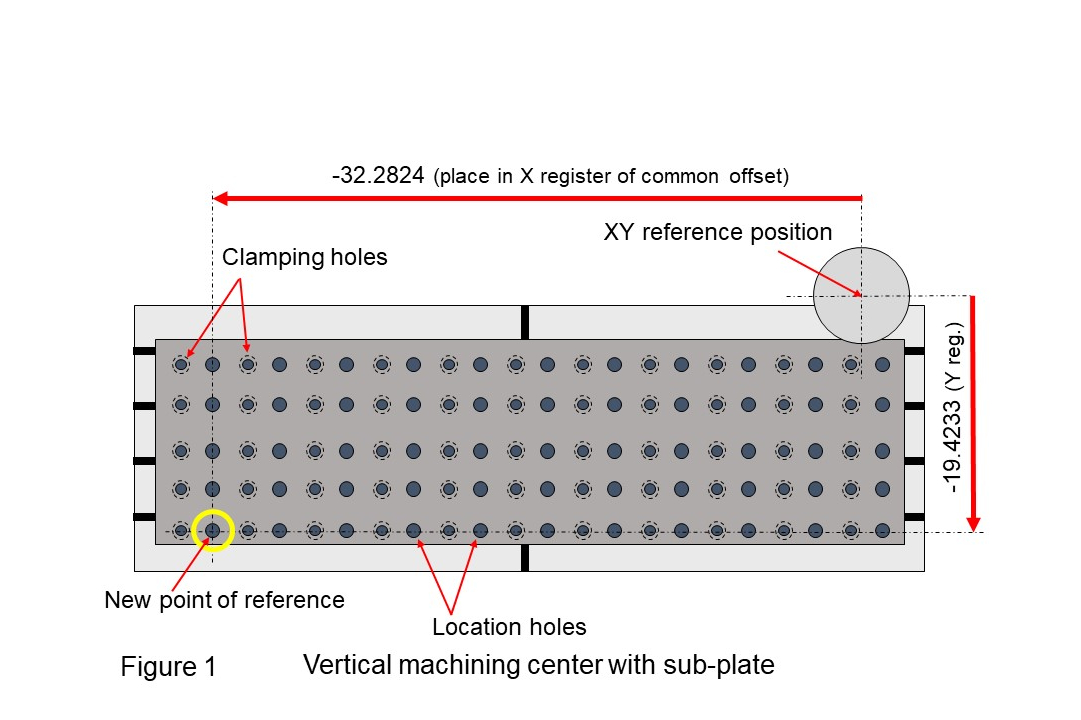
Look at the sub-plate shown in Figure 1. The location holes are all in known positions relative to one another. With component tooling, we can easily calculate the distance from the lower-left location hole to the program zero point in the X- and Y-axes. If we shift the X- and Y-axis point of reference to this location hole (by entering the distances from the reference position to the lower-left location hole into the X- and Y-axis common offset registers), program zero assignment values will make sense, and we can easily calculate them. Similarly, we can shift the Z-axis point of reference to the top of the sub-plate to make the Z-axis program zero assignment value easy to calculate. Using a G10 data setting command, we can then enter these values into their appropriate registers from within the program. This eliminates the task of program zero assignment from the list of things a setup person must do.
Similar techniques can be used with rotary devices. With a horizontal machining center, for instance, shifting the X- and Z-axis point of reference to the center of rotation — and the Y-axis point of reference to the table-top — will enable the user to calculate program zero assignment values from a known position on the fixture being used to hold the workpiece(s). Entering them with G10 commands, again, eliminates the task of program zero assignment during setup.
Shifting the point of reference for determining program zero assignment values on turning centers is done somewhat differently — and for a different reason having to do with cutting tools that remain in the turret from job to job.
The X-axis program zero point will always be the centerline of the workpiece/spindle. It does not change from job to job. So, X-axis program zero assignment values determined for one setup will remain the same for any cutting tool left in the turret for the next job.
On the other hand, the Z-axis program zero point will be a function of workpiece length if the finished end of the workpiece opposite the workholding device is chosen as the program zero point — as it often is. If we specify all Z-axis geometry offsets from the machines Z-axis reference position to a consistent surface (like the chuck face), we can then use a workpiece coordinate system offset (also called a work shift offset on turning centers) to shift the Z-axis program zero point from the chuck face to where program zero is located on the workpiece, like the right end of the finished workpiece. After doing so, and if all cutting tools remain in the machine from job to job, only the work shift value must be redetermined and reentered.


Read Next

The Cut Scene: The Finer Details of Large-Format Machining
Small details and features can have an outsized impact on large parts, such as Barbco’s collapsible utility drill head.
Read More
Obscure CNC Features That Can Help (or Hurt) You
You cannot begin to take advantage of an available feature if you do not know it exists. Conversely, you will not know how to avoid CNC features that may be detrimental to your process.
Read More
3 Mistakes That Cause CNC Programs to Fail
Despite enhancements to manufacturing technology, there are still issues today that can cause programs to fail. These failures can cause lost time, scrapped parts, damaged machines and even injured operators.
Read More