
What’s the Correct Reading?
A CMM, a bore mic and an air gage measure parts differently and may provide different values, yet all of them may be correct. Here’s how.

Share


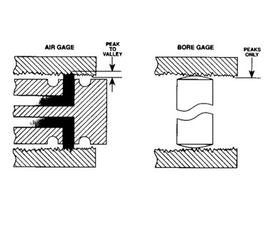
What is true size? If you are measuring a tight tolerance, you need to know and understand the surface finish of the part. An air gage averages a measuring areas whereas a mechanical contact gage is a point contact system that measures the high points.
I was recently contacted by a customer whose long-term supplier had manufactured a number of precision, hard-turned parts (0.4-0.8 Ra) inspected on the supplier’s CMM. Upon receipt of the parts, our customer used an air gage to verify the inspection results and found that more than half were outside of the specification. To verify the air gage, they used a manual bore mic, and these readings aligned themselves somewhat with those of the air gage. However, the parts measured on the CMM consistently ran 2 microns smaller than the air gage and 1 micron smaller than the bore mic readings. The questions to us was, “What’s going on?”
A CMM, a bore mic and an air gage all measure parts differently. About 90% of the time, the air plug is a two-jet plug measuring one diameter at one location. A bore mic is a three-point measuring system. But a CMM has many different routines for measuring a diameter. In the situation described above, it is most likely that numerous points were measured around the radius, and an average diameter was produced based on the user’s selection. That’s a far cry from the two points an air gage may produce and then again different than the bore mic. Beyond that, there are even more selections with the CMM — a form-type analysis for diameter could be provided and the diameter calculated on a least squared diameter (the average) or a minimum or maximum inscribed diameter. Mathematically, all may be correct but they are different values. Based on the form of the part, all are apt to produce slightly different diameter results.


In this particular case, this was what was happening as all the readings were accurate, but each one was measuring slightly different dimensions. Placing the parts on a form system revealed that the parts tended to have an even number of lobes (good for two-point measurements) and that there was a waviness of a little more than 1.5 microns. Based on the form analysis for minimum or maximum inscribed circle, there was likely 1.5 microns of potential discrepancy.
A couple of quick of checks were performed next. One was to use the minimum inscribed circle diameter as measured with the CMM instead of the least squared method. Suddenly, the correlation between the three methods got a little better — almost right on for the bore mic and the CMM. This demonstrated that the form error was enough to make a difference between the various ways of mathematically calculating the diameter with the CMM. The second check was to change the method of measuring diameter with the air plug. Instead of measuring the actual two-point diameter, the gage display was set to a dynamic mode to record the minimum diameter as the part was rotated on the gage. This again improved the correlation, but for some reason, the air gage still had 1 micron of offset.
At this point, there was now a good correlation between the bore mic and the CMM when using the minimum inscribed circle method, but the air gage was still reading slightly larger. Then the customer noted that they always verified the diameter when receiving the parts but did not mention verifying the surface finish. So we were off to the lab with a couple of parts and within minutes and a few traces later, the rest of the story revealed itself.
The surface finish that was supposed to be 0.4-0.8 Ra was, in fact, running at 1.125 microns. Air gaging uses back pressure to measure a diameter and the air jet, with its curtain of air, has to fill in the peaks and valleys of the surface it is measuring to create that back pressure. If the surface is too extreme, the air gage will read a diameter that is a little larger than the peaks, thus making the part measure larger than it actually is. For these particular parts, the surface finish exceeded the roughness callout and the recommended roughness for proper air gage measurement. If the roughness was where it should have been, the diameter would have been right on with all three methods. So in a way, the air gage was pointing to a roughness issue while the other gages were not capable of sensing this.
Most gages are accurate as delivered from the manufacturer, but every gage embraces certain limitations and assumptions.
In this case, instead of asking, “Is it accurate?” we should have been asking, “Is it appropriate?” Most gages are accurate as delivered from the manufacturer, but every gage embraces certain limitations and assumptions. When selecting a gage or a gaging method, it is essential to establish a clear objective: Do you want to account for or ignore variation due to geometry, waveform and surface finish? Do you want to know the maximum, minimum or average OD of a part?
In the past, these conditions did not happen often, and so users did not worry about them. But today’s conditions, including tighter tolerances and gages that have remarkable resolution and performance variations in part geometry and surface finish, exert proportionally more influence on measurements.


Related Content

A 100-Year-Old Measurement Tool That is Still Used Today
The reed mechanism was a breakthrough in high-precision measurement and is still used today for sub-micron or even nanometer resolution applications.
Read More
Marathon Precision’s Engineering Playground: One Shop’s Secret to Sustaining High Tech, Low-Volume and High Morale
Half an airplane on the wall, a ten-foot metal dragon, and a full-blown recording studio might not scream “manufacturing efficiency,” yet Marathon Precision proves otherwise. Here’s how forging, complex CNC operations and staff-driven creative projects combine to fuel the shop’s productivity and profitability.
Read More
Ballbar Testing Benefits Low-Volume Manufacturing
Thanks to ballbar testing with a Renishaw QC20-W, the Autodesk Technology Centers now have more confidence in their machine tools.
Read More
AI Creates CAD Files From Scan Data
While 3D visual scanners are useful, converting a visual scan to a usable CAD file can be a time-consuming process. With generative AI, it may be much simpler and faster.
Read MoreRead Next

Know the Performance Levels of Your Gages
By understanding the characteristics of three types of gages, you can choose the correct one for your application.
Read More
What Questions to Ask About Surface Finish Call-outs
All the details of the measuring process must be uncovered.
Read More
Taking A Reading on Gages
Are we taking advantage of the vast amounts of dimensional information that a gage or hand tool can produce? Certainly not if the information presented on the gage display reads only “over,” “under” or “good.”
Read More