
Assessing Surface Functionality
Smoother isn’t always better.


George Schuetz
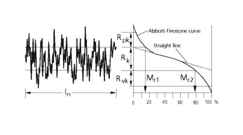
Figure 1 - If you needed to apply a coating to a surface—as in a car body panel, for example—controlling the high spot count in your process would help ensure good finish aesthetics. Peak count (RPc) is defined as the number of roughness profile peaks per a unit length that rise above some predetermined line.
Share


The science of physics has a whole branch of study—fluid dynamics—devoted to understanding how liquids and gases behave upon encountering various surfaces under differing conditions. In the dimensional metrology world, we look at things from the other side and try to understand how part surfaces behave when they encounter their counterparts and fulfill their various functions.
The traditional view throughout history was that to perform a function, a surface had to be smooth enough and if it wasn’t, it either had to be reworked or rejected. Roughness (Ra or Rz) was surface finish, and everything else was form.
Today, we know that all surface geometry—form and finish—is a function of wavelength. Short wavelength characteristics constitute roughness, and longer wavelength characteristics contribute to waviness or form. But even wavelength (frequency) is relative to part size. On some micro-sized parts, the typical 0.030-inch cutoff for a roughness trace may actually be measuring form. On that scale, a roughness reading may reflect a crown or a concavity on the part. So what is form and what is roughness depends on the scale of the parts you’re working with. We have also learned that “smoother” isn’t always better.
We also know that by controlling or manipulating surface characteristics, we can optimize part functionality. To do that, we need to understand the function of the surface and how its texture contributes to it, and we need to be able to measure those characteristics that facilitate optimization. Surfaces are often extremely complex, however, and there are many different ways to measure and analyze them. Determining what affects what can be tricky.
A classic case in point involves an automotive manufacturer who was producing a shaft with bearing surfaces specified to an Ra of less than 10 microinches. Things were going fine for a year or so, until a few shafts started seizing up in the bearings. Workers double-checked the problem shafts, and found the offending parts were all in spec but with Ra values of around 8 to 10 microinches. This was close to the limit, and previously they had proven the process out with parts that were in the 6-to-8-microinch range of Ra. Thinking that the Ra spec was even more critical than previously thought, they changed the specification to 6 microinches Ra and added a costly superfinishing operation to ensure they could meet the spec.
When they tested prototype parts from this process—all with an Ra of 3 to 4 microinches—almost every one of them seized, however. A full profile analysis of the parts revealed a longer wavelength error, likely caused by degraded shaft bearings in one of the grinding machines. Waviness had not been specified on the drawings, and all the time and money invested to make the parts smoother had only made them seize more quickly.
Another example that goes beyond simple roughness involves an aeronautical application in which a rotating engine shaft had to be sealed against oil leakage. The seal had to retain some lubricant to function, of course, but too much lubricant seeping out from under the seal would be noted as a problem during preflight inspection and possibly ground the aircraft. So the problem was perceptual, but serious nonetheless.
It was also a problem of scale. The company was using the standard 0.8-mm or 0.030-inch cutoff to analyze the surface finish of the shaft to find out how it was interacting with the seal. But the contact area of the seal with the shaft was only about 0.015 inch, so a 0.030-inch analysis tool was much bigger than the seal could “see” when it was in contact with the shaft.
Ideally, the assessment of surface functionality should happen during the design phase, and the requisite parameters and measurement conditions specified on the part prints. A properly given parameter in an engineering drawing should say what parameters are to be measured, what the high or low limits are, and how to measure (what cutoffs to use or whatever other conditions pertain, such as a cutting depth below the peak).
For example, on a surface designed to be coated, such as a car body panel, controlling high peak count would help ensure good surface aesthetics. The peak count (RPc) parameter determines the number of roughness profile peaks per unit length that rise above some predetermined line (Figure 1). On the other hand, if two surfaces need to be sealed with a gasket, longer spacing is better than short, as the gasket will be more readily able to bend and conform. If the peaks are too close together, the gasket material will leave gaps. In this case, mean spacing (Sm) would be a good choice. Furthermore, morphological filters now available in the new ISO 16610 standard provide an excellent means to filter a surface and determine how a gasket will be able to conform to the peaks on a surface.


Read Next

OEM Tour Video: Lean Manufacturing for Measurement and Metrology
How can a facility that requires manual work for some long-standing parts be made more efficient? Join us as we look inside The L. S. Starrett Company’s headquarters in Athol, Massachusetts, and see how this long-established OEM is updating its processes.
Read More