
Put Master Deviation to Use
Incorporating it into your master rings will boost measurement accuracy— an advantage in a manufacturing environment where every microinch counts.

Share


As a manufacturer of master rings, we get to see firsthand all the issues related to making a very precise hole in a round piece of steel. In addition to addressing manufacturing and inspecting of the hole to ensure it meets exceptionally tight tolerances, we must also ensure that the customer chooses the right rings with the right grade to balance performance and cost.
In this column, we have written a number of times about choosing the right grade master for the application, but this time let’s focus specifically on using the master information to your advantage.
The Measurement Process
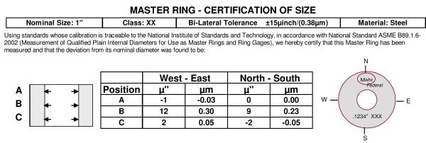
Master deviation is most commonly associated with masters and their certification reports. The certification report indicates the actual size of the master and how much it deviates from the required nominal size to which it was manufactured. Master rings are measured at three heights within the diameter and at two positions 90 degrees to each other (north-south and east-west, usually relative to the logo on the master) to give an indication of the geometry of the master. This makes a total of six deviations on the certification, which raises the question of which one to use.
To get the best use of the master deviation, the operator should be given clear instructions on how to place and orient the master on the gage when it is time to re-zero the system. When using a master, the measuring contacts should be placed near the middle of the master. The gage contacts or air jets are oriented to the north-south position of the master. As shown in the table below, north is commonly indicated by the manufacturer’s logo, and south by the nominal size and class of the master. Based on this positioning, the actual size of the master at the middle depth (B) is 1.000009 inches (25.40023 mm). The location where the master is measured isn’t as important as is the consistency of the location used. You could choose any one of the six recorded locations. For proper gaging, each operator should always locate the contacts of the gage to the same location and orientation in the master.
Using the Information
Now that we have the measuring process under control, we can start to put the power of this information to use. If this was a gage with a manual zero adjustment, the operator would put the master on the gage with the proper orientation and then adjust the zero control until the gage reads the master deviation noted at the specified location.
Many digital products (dial indicators and amplifiers) are capable of incorporating the master deviation into the measurement itself. Digital indicators with “preset” input can enter the true master size for actual size results (1.000009 inches) or, if performing a comparative measurement, can enter the deviation value (0.000009 inch). Electronic amplifier and air systems use features such as “nominal” or “actual” to enter the part’s nominal size (1.000000 inch) and use a separate entry for the master size such as “master” (1.000009 inches), “deviation” (0.000009 inch) or “master deviation” (0.000009 inch).
Every Microinch Counts
The advantage of using master deviation is that the true part size is being measured. Including master deviation in the measurement will make statistical process control (SPC) data more relevant and achieve better control of the process. This is especially important when master size is significantly different from nominal size. Masters may wear over time and use, or may be difficult to produce to a true nominal size.
It should be pointed out here that since most master deviations are in tens of microinches or less, they are best used when tolerances are tight and every microinch counts.
But in today’s manufacturing environment it’s becoming clear that every microinch already counts. There is a reason why electronic devices allow for master deviation, so you should take advantage of the information you have and improve your process.


.png;maxWidth=300;quality=90;format=webp)


Read Next

OEM Tour Video: Lean Manufacturing for Measurement and Metrology
How can a facility that requires manual work for some long-standing parts be made more efficient? Join us as we look inside The L. S. Starrett Company’s headquarters in Athol, Massachusetts, and see how this long-established OEM is updating its processes.
Read More