Applying Turn-Milling
Combining a rotating tool with rotating work produces a machining operation that is distinct from standard turning or milling.
Share


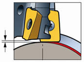
The wiper insert follows and protrudes below the insert that does the cutting. The purpose of the wiper is to smooth out the surface.
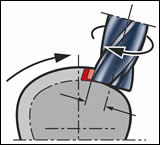
Cutting off-center from the work's axis of rotation ensures that the cutting edges engage properly.
Here are three tools that can be used effectively in turn-milling, in part because of their use of wiper inserts or edges. The face mill (top) is for turn-milling involving large surfaces or heavy interrupted cuts. The inserted end mill (middle) performs shoulder milling. The solid-body end mill (bottom) is for turn-milling in circumstances that would typically call for a solid-body tool, such as finishing and milling small slots. This last tool realizes its wiper effect through a design in which two of the four cutting edges reach deeper into the part.
"Turn-mill" can be an ambiguous term. Turning centers with rotary-tool capability are sometimes called turn-mill machines. But at the same time, there is a specific metalworking operation performed on these machines that rightly deserves to be called "turn-milling." This involves cutting with a rotating milling tool while the workpiece is also rotating.
There are many reasons why a shop might want to machine this way. Chip control is one. Dealing with interrupted cutting is another. At least one cutting tool supplier—Sandvik Coromant—now sees turn-milling employed so frequently that the company has developed cutting tools specifically for this operation. Sandvik product specialist Jim Grimes, who provided the information for this article, says that with sophisticated multitasking lathes coming into greater use, turn-milling can no longer be thought of as such an unusual way to cut. Today's users of turn-mill machines should be thinking about this style of cutting in many cases where they struggle with standard turning.
Featured Content

When To Turn-Mill
Here are some of the specific challenges that turn-milling can address:
- High metal removal. If a turned part requires a lot of material to be removed, turn-milling may be able to do this more efficiently.
- Interrupted cuts. Turning tools tend not to do well in interrupted cutting, but a milling tool can fare much better. A milling cut is already an interrupted cut by definition. In the region of the workpiece where the cut becomes interrupted, it may make sense to switch from turning to turn-milling.
- Stringing chips.The "bird's nest" produced by the stringing chip in some materials won't build up when the part is turn-milled instead of turned. One consequence of milling's inherently interrupted cut is that chips are cut into small pieces.
- Flexible shafts. When the turned part is long, slender and not braced in the middle, turn-milling may prevent it from deflecting. Compared to turning, milling can remove the material with less tool pressure.
- Tool life. In a hard-to-machine metal, a single turning insert might not be able to deliver enough tool life to last to the end of the cut. A milling tool can cut longer, because it has multiple inserts to divide the load. By enduring the complete cut, the milling tool can eliminate the risks involved with changing tools in mid-operation.
- Eccentric diameters or odd shapes. The radial (X-axis) motion of the milling cutter can be coordinated with the rotation of the workpiece to machine profiles other than perfect circles. Sandvik itself uses this technique to rough-machine the three-lobed, tapered shape of its "Capto" toolholders. The same principle—the milling cutter moving in and out while the workpiece turns—can also be used to generate off-center features without having to change the setup. The off-center pin on a crankshaft could be an example of this.
Turn-Milling Technique
Turn-milling is not particularly demanding of the machine tool, but at minimum the process does require Y-axis motion.
Workpiece rotation provides the C-axis motion that delivers the desired feed rate for the milling cutter. Instead of sfm, in other words, the rotation speed is chosen for a particular ipm. (That means the workpiece speed in turn-milling is much slower than what is typical of turning.)
Y-axis motion is needed because the milling cutter has to do most of its cutting off-center. The tool can't machine the part to size when it is on-center—when the tool centerline intersects with the axis of rotation of the part—because then the tool would be cutting on the center of its face and not on its edges. To ensure that the cutting edges cut properly, the tool centerline should be offset from the work's axis of rotation by 1/4 of the cutter diameter.
The problem with cutting this way occurs when the tool reaches a shoulder or the side of a groove. The off-center tool leaves a rounded corner behind.
To achieve a sharp corner, the cutter must take a second pass. The offset is eliminated, so the tool moves back to the on-center position in Y. This second pass performs no material removal except for what is necessary to clean the corner material away.
One fact of life in turn-milling is form error. Milling around the circumference of a round form inevitably leaves regularly spaced scallops in the surface. This error can't be eliminated altogether, but it can be controlled using wiper inserts. A wiper insert is an insert that follows along behind the cutting edge, extending just a little farther into the material to smooth out the freshly cut surface.
Mr. Grimes says his company's development of tools for turn-milling has focused on wiper design. The wiper makes the scallop error controllable, because formulas associated with a particular wiper let users adapt their turn-milling parameters to achieve whatever level of error is acceptable.
Force And Deflection
One wiper-equipped tool is a solid-body end mill that gets its wiper effect from having two of the four flutes reach deeper into the part. A secondary benefit of this tool design is that it redirects the cutting force in a beneficial way. In turn-milling, as the work rotates up to meet the tool, some of the cutting force pushes along the tool's axis. Having only two active flutes on the bottom reduces this axial component of force, so more of the cutting force is pushing in the tool's radial direction.
The fact that this change is beneficial points out how different turn-milling is from milling in general. In a more standard milling application, sending force along the tool's axis can be good. The work is well supported in this direction. But in turn-milling, where the work may be long, slender and supported only at the two ends, it is the tool's axial direction that presents the greater risk of harmful chatter. Making the best use of forces in this application calls for an altogether different design of the tool.


Related Content

Shoulder Milling Cuts Racing Part's Cycle Time By Over 50%
Pairing a shoulder mill with a five-axis machine has cut costs and cycle times for one of TTI Machine’s parts, enabling it to support a niche racing community.
Read More
Briquetting Manufacturer Tools Up for Faster Turnaround Times
To cut out laborious manual processes like hand-grinding, this briquette manufacturer revamped its machining and cutting tool arsenal for faster production.
Read More
Choosing the Right Drill Type
Specifying the right option for your application can save time and tools.
Read More
Measuring Torque, Thrust Force for Smart Drilling Operations
To monitor drilling operations for smart manufacturing solutions, torque and thrust force can be measured.
Read MoreRead Next

OEM Tour Video: Lean Manufacturing for Measurement and Metrology
How can a facility that requires manual work for some long-standing parts be made more efficient? Join us as we look inside The L. S. Starrett Company’s headquarters in Athol, Massachusetts, and see how this long-established OEM is updating its processes.
Read More