
Automating the Indicator Calibration Process
Eliminate human error when calibrating precision hand tools by leveraging modern vision systems.

Share


All gaging equipment must be calibrated periodically to ensure that it is capable of measuring parts accurately. This is true for every hand tool or gage used in a manufacturing environment that verifies the quality of parts produced. This has always been necessary for maintaining quality, but there are also additional, external reasons to establish and maintain a regular program of gage calibration, mainly customer requirements. It is now common that companies request suppliers to document their quality efforts from start to finish.
Some large companies with thousands of hand measuring tools, dial/digital indicators and comparators can justify the cost of hiring or training specialists in gage calibration methods and supply them with equipment to perform in-house calibration. However, dial and digital indicator or comparator calibration can be a very time-consuming and operator-intensive process.


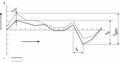
Example of points required for checking an indicator.
Most dial indicators are relatively short-range but need to be checked at multiple points throughout their range to verify performance accuracy. They then need to be checked again in the reverse direction to verify hysteresis requirements. Historically, most dial indicator calibrators have been built around a high-precision mechanical micrometer, in effect, turning the micrometer to a known point and then observing any deviation on the dial indicator. Even for a short-range indicator, the process will involve moving a mechanical dial calibrator by hand to 20 or more points along the indicator’s travel. This is not too difficult for a short-range indicator, but with a longer-range indicator, say 12.5, 25, 50 or even 100 mm of range, there are a lot of positions to go to and points to observe and record.
This can also take a significant amount of time and concentration by the user. Doing this for many indicators throughout the day is stressful for the operator not only in hand-positioning the micrometer head to hundreds if not thousands of points, but also the resulting eye strain from reading the micrometer head and the indicator. The reading is also problematic since people will naturally (unintentionally) reverse numbers or just misread. Alternatively, in the case of a dial indicator, not reading the indicator straight on causes a parallax effect and a misreading of the result.
In order to reduce operator stress and increase productivity, automated calibrators are available that, based on the indicator, will drive a precision spindle to the desired location. The operator can then read and record the deviations. These machines will significantly reduce the hand/arm strain caused by the constant rotational driving of the micrometer head. This is a significant improvement. However, there are better options.
The real improvement would be to eliminate the operator by installing the indicator into a calibration tool, setting the parameters within the gage for the indicator, and then letting the gage measure and certify the indicator without operator involvement. This allows the gage technician to be productive preparing the next indictor to be checked, signing the indicator certifications, or even starting another calibration process while the automated calibrator is working.
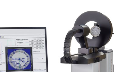
Systems can “read” the indicator to capture its values.
With today’s modern vision systems, it is possible to “read” the dial/digital indicator or comparator. By read, I mean the vision system can actually know what the indicator and the dial should be and process an image to read the pointer relative to the graduations and interpolate this as a measurement. In the case of digital indicators, the digital dial is scanned by the system's camera, the digits are analyzed/“read” by the controller and the actual deviation between measurements is made.
Because of this automation with image processing, what once was a labor-intensive process with a high risk of error is now faster. Also, it reduces uncertainties while preventing potential stress and injuries to the operator. With the auto-recognition of the vision system, more test items with more data points will be recorded faster than conventional, manual methods. This frees the operator to be productive during the automated measuring process.


.png;maxWidth=300;quality=90;format=webp)
Related Content

Marathon Precision’s Engineering Playground: One Shop’s Secret to Sustaining High Tech, Low-Volume and High Morale
Half an airplane on the wall, a ten-foot metal dragon, and a full-blown recording studio might not scream “manufacturing efficiency,” yet Marathon Precision proves otherwise. Here’s how forging, complex CNC operations and staff-driven creative projects combine to fuel the shop’s productivity and profitability.
Read More
A Balancing Act for Differential Gaging
Differential gaging measures using two devices, which has advantages over standard, comparative measurements using a single sensing head. These include the ability to measure size without regard to position.
Read More
Using Air to Measure Squareness
Though most frequently used for diameter measurements, an air plug and platen can be readily configured to measure perpendicularity.
Read More
Machined Part Geometry Measurement
Uncertain about uncertainty? Having trouble remembering the difference between accuracy and precision? Read on to review key metrology terms relevant to the ISO Guide to the Expression of Uncertainty in Measurement (ISO GUM).
Read MoreRead Next

Portable Surface Gaging in a Production Environment
Handheld portable surface gages are easy to use. But that doesn’t mean there aren’t challenges when scanning hundreds or even thousands of parts.
Read More
How To Calibrate Your Calipers
If you’re interested in calibrating your own digital, dial or Vernier calipers, here are some steps to take to make sure it goes off without a hitch.
Read More
How To Measure Surface Roughness on Large Parts
Performing surface finish measurements on large or complex parts can be made much easier with properly designed fixturing.
Read More